18. Fan replacement procedures
Image 18-15
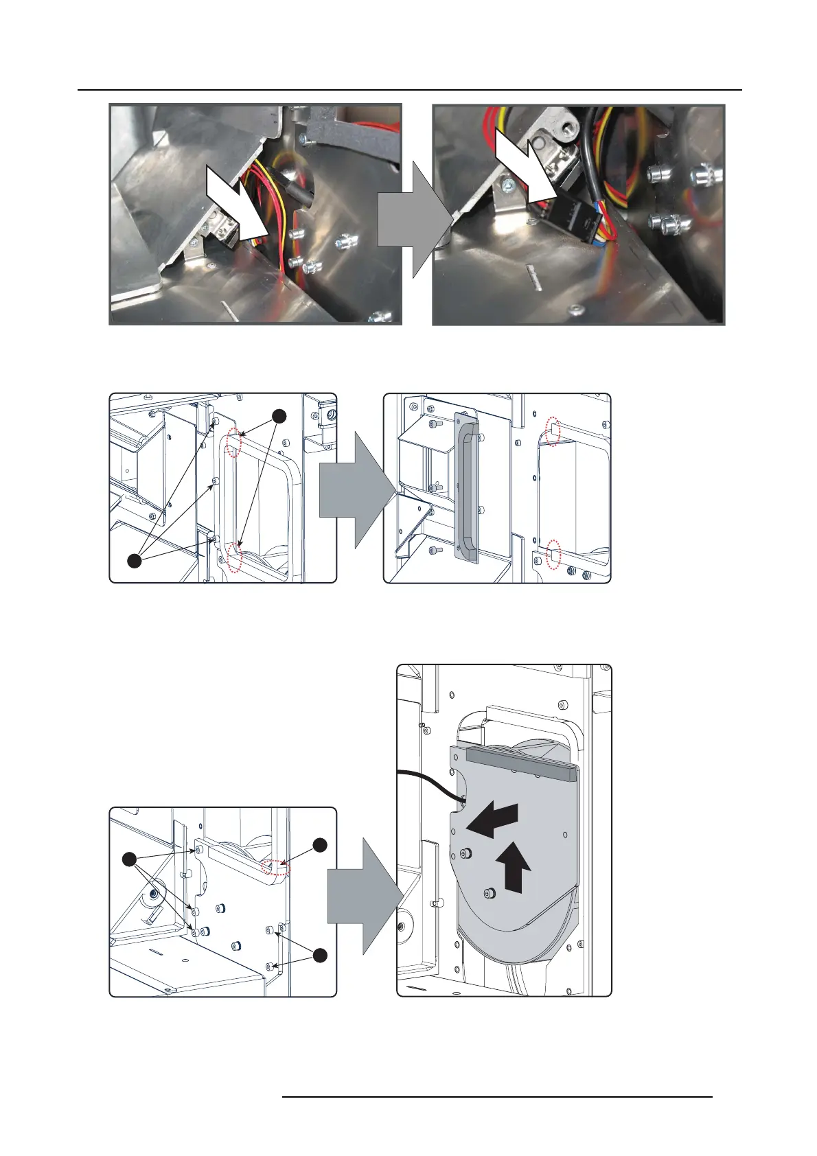
Cathode fan, power disconnection
3. R emov e the small side p late of the air channel by releas ing the three screws (reference 2). C ut the foam rubber (reference 3)
as it is stuck on d ifferent plates.
2
3
Image 18-16
Small side pla t e, removal
4. R emov e the cathode fan assembly out of its compartment by releasing the five indicated screws (reference 4). Cut the foam
rubber (reference 5) as it is s tuck on different plates.
Tip: Lift up and slightly turn the fan assembly to remove.
4
4
5
Image 18-17
Cathode fan assembly removal
5. D isassemble the cathode fan assembly by removing the fi ve indicated screws (reference 6).
R5905312 HDF W SERIES 24/01/2013
297

 Loading...


