18. Fan replacement procedures
Image 18-32
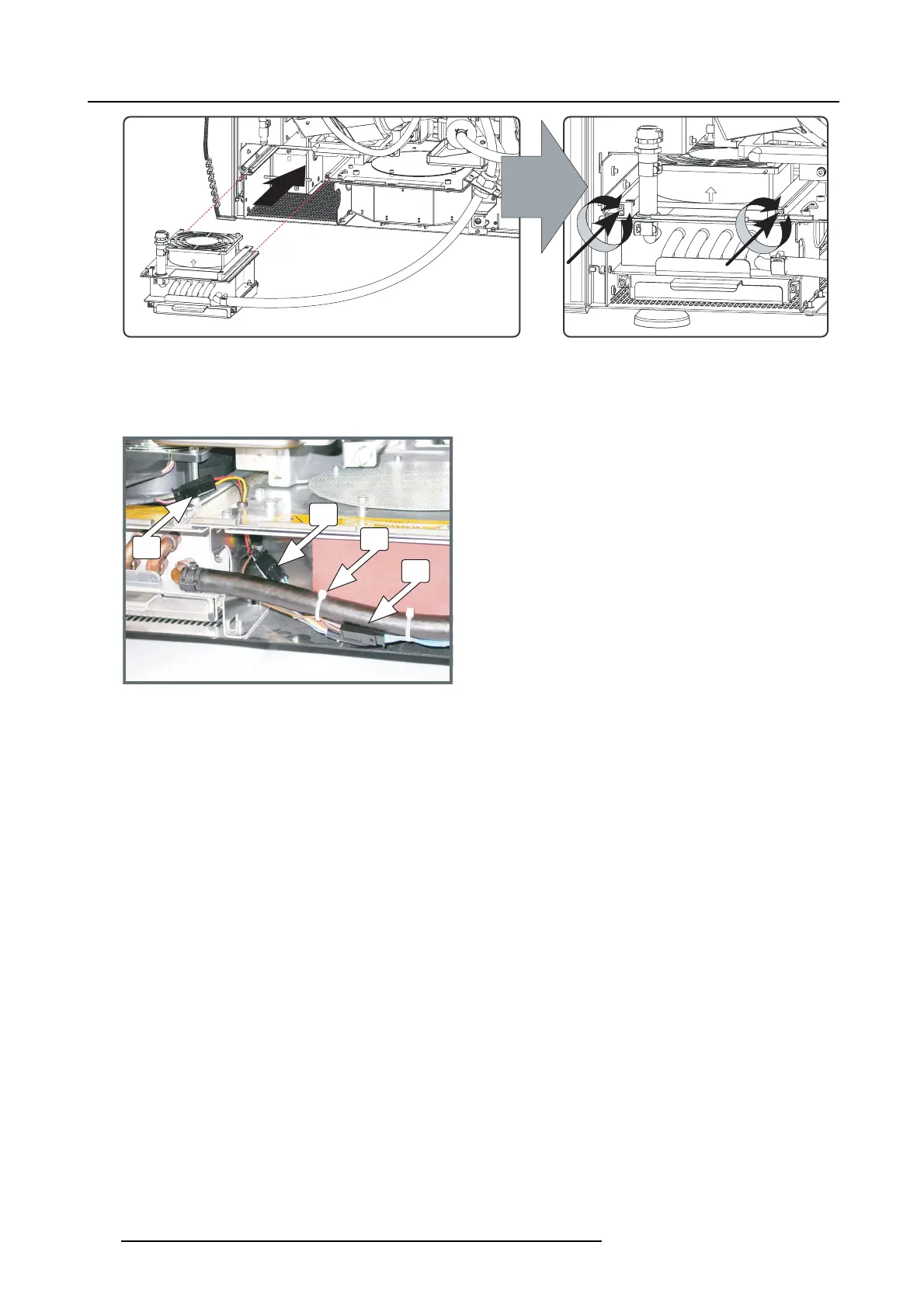
Insert heat exchanger assembly
11.Insert th e c ooling fixation into the plate.
12.R econnect the wire unit of the anode fan (reference B), the wire unit of the heat exchanger fan (reference A) and the wire unit of
the p ump (reference C). Use a cable tie (reference D) to secure the wire unit of the pump with the tubing.
C
B
D
A
Image 18-33
Electrical connection
304 R5905312 HDF W SERIES 24/01/2013

 Loading...


