Chapter 4: Installation and Setup
Start Switch Connection (Automation)
4-34 011-003-991 EN
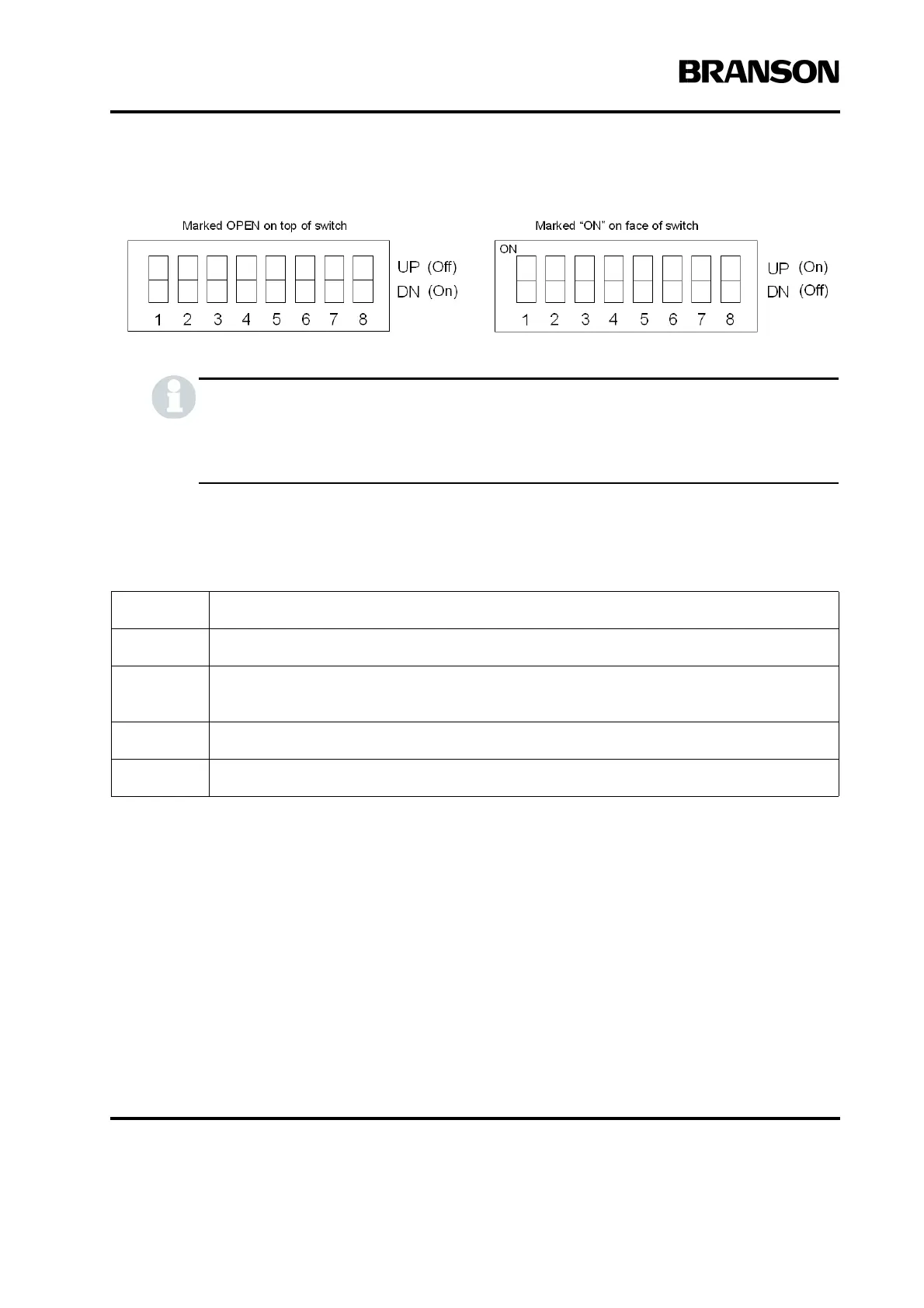
Figure 4.15 Switch Select Block
This switch controls circuits which are based on negative logic. This means that turning a
switch position to Off will actually be turning a circuit on, and turning a switch position to On
will be turning a circuit off
Refer to Table 4.9
To change Power Supply Module DIP switch settings, take the following steps*:
*It is not necessary to remove the Control Board to change the DIP settings.
Step: Action:
1 Turn off and unplug the Power Supply.
2
Open the Power Supply by removing the seven screws on the cover (three on each side,
and one in the rear). Remove the cover and set it aside.
3 Locate the DIP switches and default settings as shown in Figure 4.14.
4 Change the DIP switch settings to suit your application requirements (Refer to Table 4.9).