© AGRGS 2016 | Data subject to change without notice
67385867493098462 | en, eu, V5, 07. Oct 2016, page 111
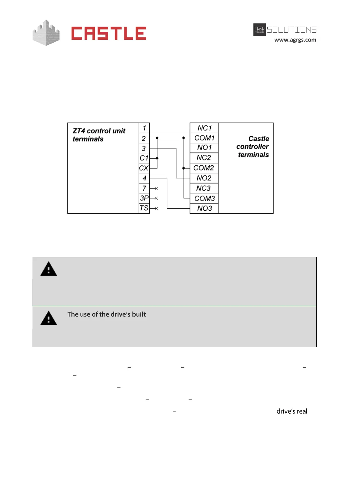
«X» sign in the "Toggle position" means that this switch performs the function that does not affect
the ACS operation, and it must be put in the required position according to the original instruction
for ZT4 control unit.
If you use two drives in the "Master & Slave" mode, connect the controller and set the micro toggle
switch according to the above table only on the master control unit. Then the second drive is
connected and switched to the slave mode according to the original instruction for ZT4 control
unit.
Pic 103. Connecting to ZT4 control unit
The rest of the unit terminals (R, S, T, U, W, V, E, E1, EX, 5, 6, 10, 11, E4, B1, B2, MOT, F, FA, FC) are
connected according to the original instruction for ZT4 control unit.
All vehicle presence sensors, as well as manual control panel, should be connected
exclusively to the controller, and not to the barrier drive or to both of them.
Violation of this requirement may lead to different conflicts ranging from passage
registration failure to "freezing" the barrier beam in the intermediate states to
eventual damage of a passing vehicle.
-in radio receiver is forbidden. Command submission
bypassing the ACS controller will sooner or later lead to a damage of a passing
vehicle. For controlling the drive via remote keys, you should use Wiegand
interface radio receivers connected to the ACS controller.
Before enabling the access point, you need to make its mandatory settings.
To do this, run Control Program select Doors tab select the desired controller from the list
click Settings uncheck Show only basic settings. Then make the following settings:
● Gate control mode select Open, Close, Stop. Logic «B».
● Gate control impulse length set within 0.4 0.5 seconds.
● Max open/close time of gate sections set equal to about 1.1 times of the
opening (closing) time. E.g., if it opens fully within 5 seconds, then the parameter value
must be equal to 5.5 seconds.