© AGRGS 2016 | Data subject to change without notice
67385867493098462 | en, eu, V5, 07. Oct 2016, page 114
The function selection micro toggle switch on the ZA3 control unit board should be set in the
position described in the following table.
Table 87. Setting the function selection micro toggle switch on the ZA3 control unit board
«X» sign in the "Toggle position" means that this switch performs the function that does not affect
the ACS operation, and it must be put in the required position according to the original instruction
for ZA3 control unit.
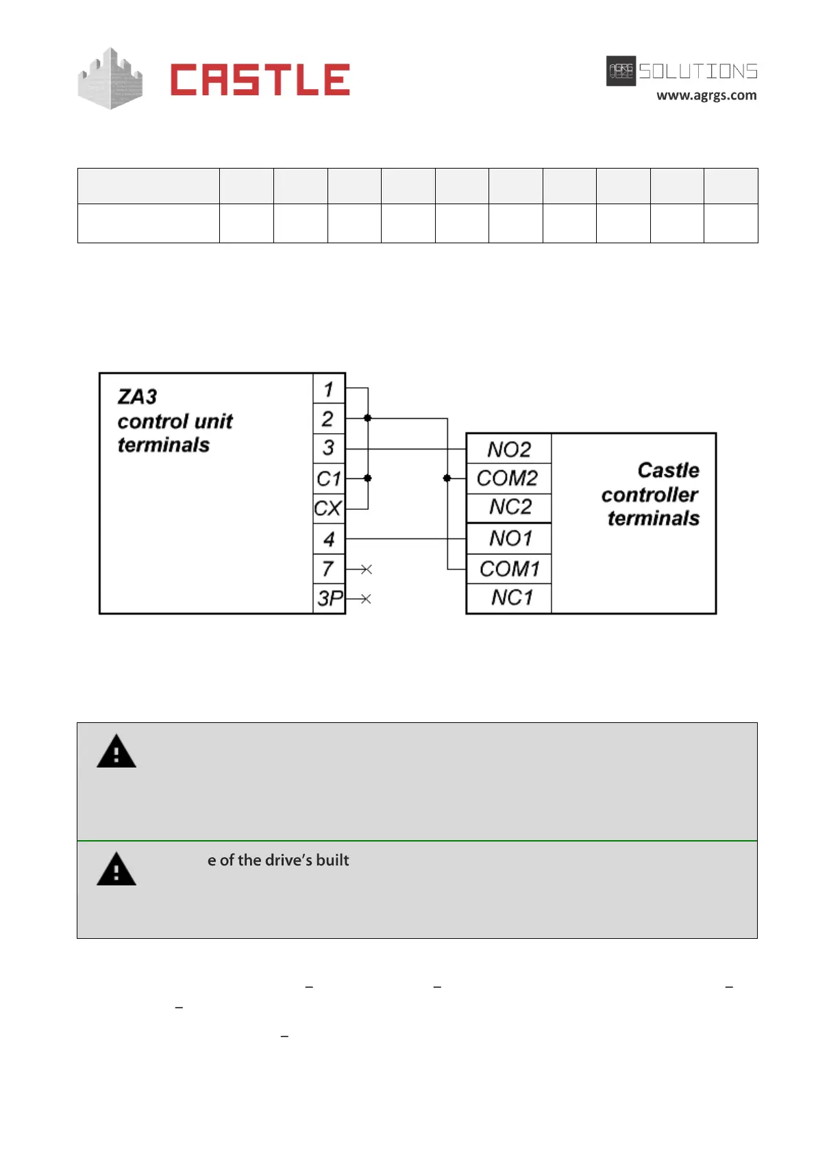
Pic 105. Connecting to ZA3 control unit
The rest of the unit terminals (L1, L2, U, W, V, X, W, Y, E, E3, 5, 10, 11, S, B1, B2) are connected
according to the original instruction for ZA3 control unit.
All vehicle presence sensors, as well as manual control panel, should be connected
exclusively to the controller, and not to the barrier drive or to both of them.
Violation of this requirement may lead to different conflicts ranging from passage
registration failure to "freezing" the barrier beam in the intermediate states to
eventual damage of a passing vehicle.
The us -in radio receiver is forbidden. Command submission
bypassing the ACS controller will sooner or later lead to a damage of a passing
vehicle. For controlling the drive via remote keys, you should use Wiegand
interface radio receivers connected to the ACS controller.
Before enabling the access point, you need to make its mandatory settings.
To do this, run Control Program select Doors tab select the desired controller from the list
click Settings uncheck Show only basic settings. Then make the following settings:
● Gate control mode select Straight drive direction (Direct drive control) from the drop-
down menu.