© AGRGS 2016 | Data subject to change without notice
67385867493098462 | en, eu, V5, 07. Oct 2016, page 129
The toggle selects the normal state of the control STOP button. ON normally closed,
OFF normally open. For the wiring diagram of the control panel, refer to Sec. 10.5 Connecting the
gate control panel.
The toggle selects the configuration of vehicle presence sensors. ON only one (the central) is
connected, OFF all three are connected (at the entrance, in the center and at the exit). For the
wiring diagram of vehicle presence sensors, refer to Sec. 10.6 Connecting vehicle presence sensors.
LYNX 06 control unit should be programmed as follows:
The items marked with «X» can be left in arbitrary state.
The items marked with «S» are not fundamental for the ACS operation, and they should be
programmed according to the original instruction for LYNX 06 control unit.
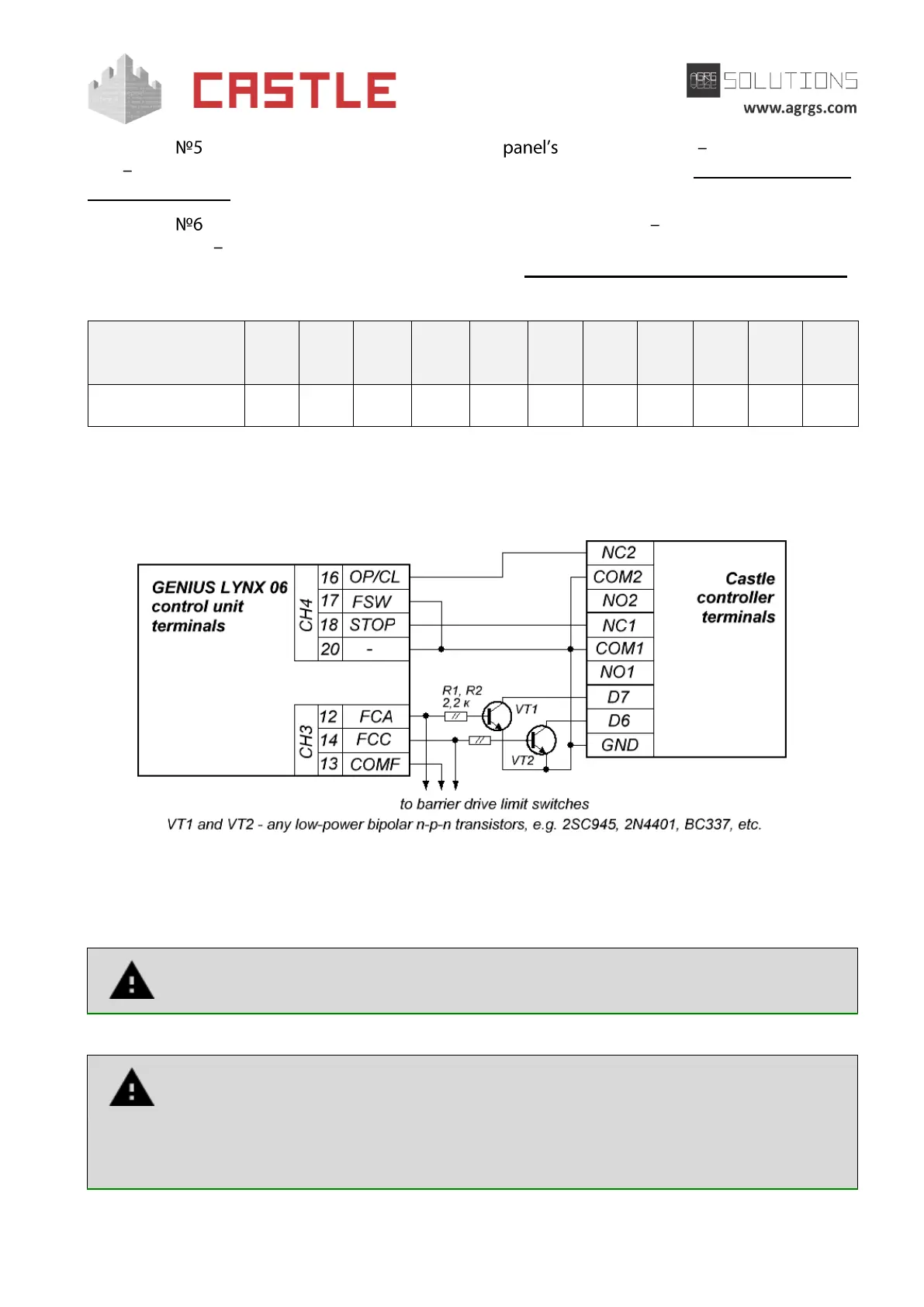
Pic 115. Connecting to LYNX 06 control unit
The rest of the unit terminals are connected according to the original instruction for LYNX 06
control unit.
Attention! In addition to the controller, limit switches for opening and closing a
drive are connected to terminals FCA, COMF, and FCC.
All vehicle presence sensors, as well as manual control panel, should be connected
exclusively to the controller, and not to the barrier drive or to both of them.
Violation of this requirement may lead to different conflicts ranging from passage
registration failure to "freezing" the barrier beam in the intermediate states to
eventual damage of a passing vehicle.