© AGRGS 2016 | Data subject to change without notice
67385867493098462 | en, eu, V5, 07. Oct 2016, page 140
The toggle selects the normal state of the control STOP button. ON normally closed,
OFF normally open. For the wiring diagram of the control panel, refer to Sec. 10.5 Connecting the
gate control panel.
The toggle selects the configuration of vehicle presence sensors. ON only one (the central) is
connected, OFF all three are connected (at the entrance, in the center and at the exit). For the
wiring diagram of vehicle presence sensors, refer to Sec. 10.6 Connecting vehicle presence sensors.
You should set the «B» operating logic of the drive. To do this, push SW1 button twice on the
SHAFT-30 control unit board. The interval between two pushes must be less than a second. After a
timeout of more than one second, the number of pushes will have been stored in the unit (DL1 LED
shall flash twice).
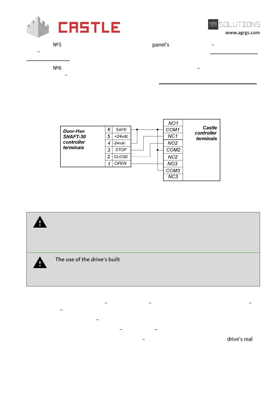
Pic 123. Connecting DoorHan SHAFT-30 control unit
The rest of the unit terminals (mains, electric motor, limit switches) are connected according to the
original instruction for SHAFT-30 control unit.
All vehicle presence sensors, as well as manual control panel, should be connected
exclusively to the controller, and not to the barrier drive or to both of them.
Violation of this requirement may lead to different conflicts ranging from passage
registration failure to "freezing" the barrier beam in the intermediate states to
eventual damage of a passing vehicle.
-in radio receiver is forbidden. Command submission
bypassing the ACS controller will sooner or later lead to a damage of a passing
vehicle. For controlling the drive via remote keys, you should use Wiegand
interface radio receivers connected to the ACS controller.
Before enabling the access, you need to make its mandatory settings.
To do this, run Control Program select Doors tab select the desired controller from the list
click Settings uncheck Show only basic settings. Then make the following settings:
● Gate control mode select Open, Close, Stop. Logic «B».
● Gate control impulse length set within 0.4 0.5 seconds.
● Max open/close time of gate sections set equal to about 1.1 times of the
opening (closing) time. E.g., if it opens fully within 10 seconds, then the parameter value
must be equal to 11 seconds.