© AGRGS 2016 | Data subject to change without notice
67385867493098462 | en, eu, V5, 07. Oct 2016, page 148
The toggle selects the configuration of vehicle presence sensors. ON only one (the central) is
connected, OFF all three are connected (at the entrance, in the center and at the exit). For the
wiring diagram of vehicle presence sensors, refer to Sec. 10.6 Connecting vehicle presence sensors.
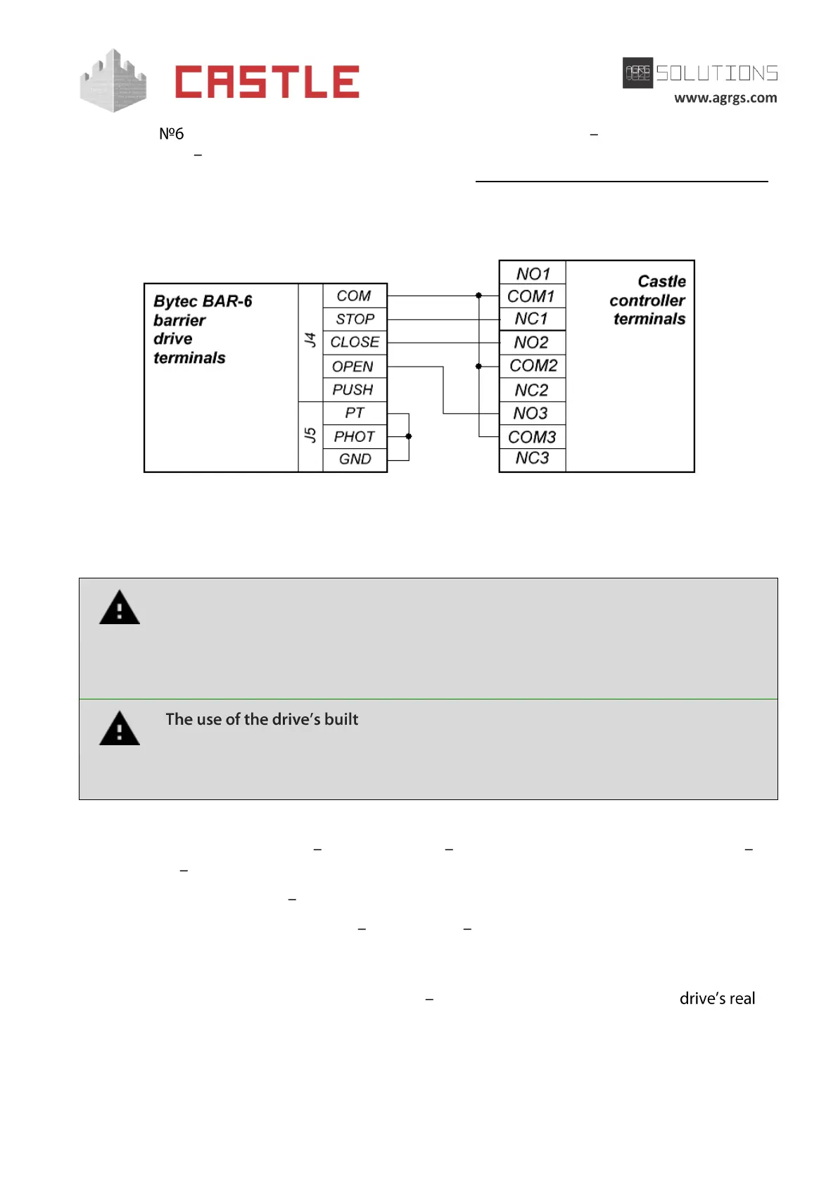
On the Bytec BAR-6 control unit board, turn S1 DIP1 switch (or S5, depending on the control unit
version) in OFF position, thus disabling the automatic barrier lowering.
Pic 128. Connecting Bytec BAR-6 control unit
The rest of the unit terminals (mains, electric motor, limit switches) are connected according to the
original instruction for Bytec BAR-6 control unit.
All vehicle presence sensors, as well as manual control panel, should be connected
exclusively to the controller, and not to the barrier drive or to both of them.
Violation of this requirement may lead to different conflicts ranging from passage
registration failure to "freezing" the barrier beam in the intermediate states to
eventual damage of a passing vehicle.
-in radio receiver is forbidden. Command submission
bypassing the ACS controller will sooner or later lead to a damage of a passing
vehicle. For controlling the drive via remote keys, you should use Wiegand
interface radio receivers connected to the ACS controller.
Before enabling the access point, you need to make its mandatory settings.
To do this, run Control Program select Doors tab select the desired controller from the list
click Settings uncheck Show only basic settings. Then make the following settings:
● Gate control mode select Open, Close, Stop. Logic «B».
● Gate control impulse length set within 0.4 0.5 seconds. After that, make sure that the
drive accepts all the commands submitted to it by the controller without missing any of
them. In case of omitting commands, increase the pulse duration.
● Max open/close time of gate sections set equal to about 1.1 times of the
opening (closing) time. E.g., if it opens fully within 5 seconds, then the parameter value
must be equal to 5.5 seconds.
● Max waiting time before autoclosing an opened gate is the waiting time for a vehicle
to start passing the barrier after the drive is fully open. Set as desired.