© AGRGS 2016 | Data subject to change without notice
67385867493098462 | en, eu, V5, 07. Oct 2016, page 69
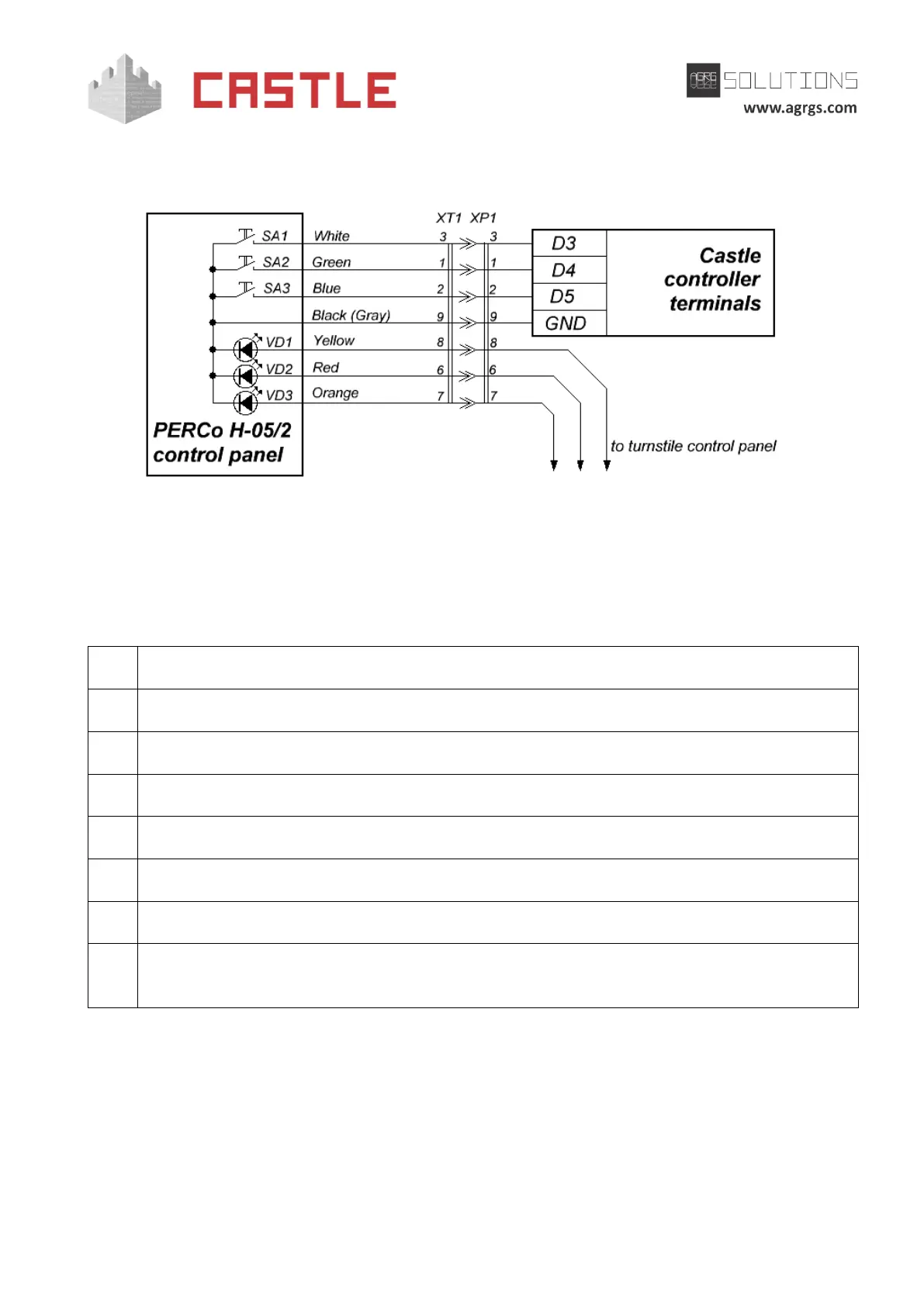
Note: colors of the console wires can vary from the supply, for correct connection consult the
documentation of the turnstile.
Pic 49. Connecting PERCo H-05/2 control panel with a socket
You can connect the console wires directly to controller terminals, if required. At the same time, it
should be noted that the colors of the wires on the diagram are shown for estimation only. For
proper connection, keep in mind the compliance of wires and plug contacts.
Legend:
Normally open A button of the panel
Normally open B button of the panel
Normally open STOP button of the panel
DB-9M plug of the control panel
DB-9F socket to create Control-panel-to-Castle-controller adapter; it is not included in the
package.
For the PERCo-TTR-04N and TTR-04W turnstiles, there are two options for connecting control panel
buttons.
1. Directly to the turnstile control panel. In this option, passages authorized by pressing
buttons will be recorded in the ACS as the break-ins, but you will be able to manually
enable free passage mode in one or both directions.