S0602170K
Page 118
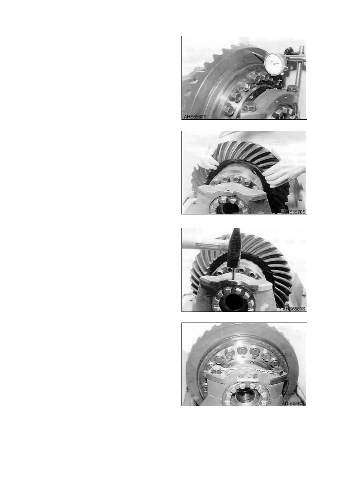
Axle (ZF AP 420R)
6. Attach dial indicator on the plane face/
crown wheel.
7. Make at least one revolution of the crown
wheel and record the run-out.
NOTE:
Admitted run-out max. 0.08 mm
(0.0031 in).
NOTE:
See “Special Tools” on page 15.
8. Cover some tooth flanks of the crown
wheel wish gear marking compound.
9. Roll the crown wheel over the drive pinion
back and forth.
10. Check the contact pattern and compare it
with “Examples of Gear-tooth-contact
Patterns for the Gleason Gear-tooth
System” on page 11.
11. In case of a greater contact pattern
deviation, a spacing error has been made
during the reassembly of the drive pinions
which must be corrected.
12. Secure adjusting nut.
13. Secure adjusting nut and hex. head
screws according to the Figure 286.
Figure 283
Figure 284
Figure 285
Figure 286