S0607080K
Page 156
Transmission and Torque Converter
(ZF 4WG-310)
2. The following illustrations describe the
reassembly, resp. the setting of the
Inductive transmitter N engine (14, Figure
401). The reassembly of the Inductive
transmitter N turbine (6, Figure 401) and N
central gear train (39, Figure 401) has to
be carried out accordingly.
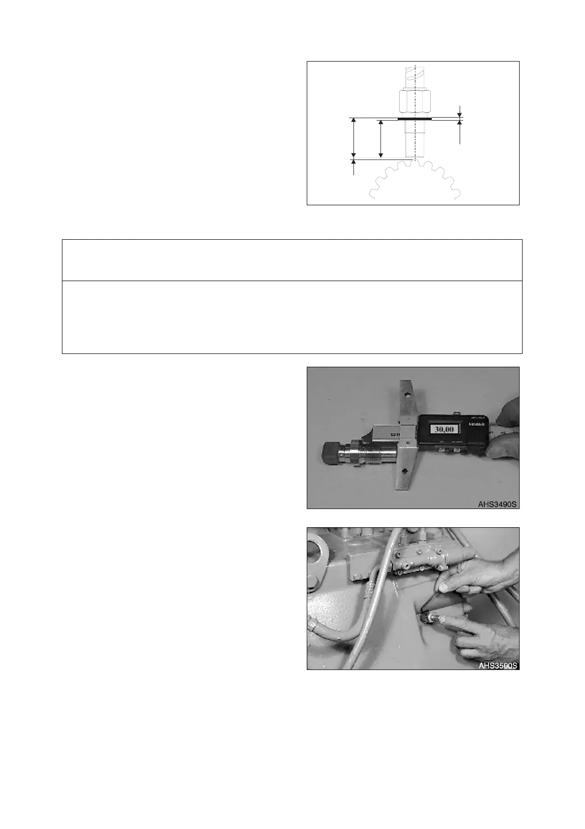
3. Set Dimension X using adjusting disk(s)
(Figure 404 - Figure 410).
A. Measure Dimension I from the
contact face to the screw-in face on
the inductive transmitter.
NOTE:
Dimension I e.g. 30.00 mm
(1.1811 in).
B. Rotate counting disk radially until one
tooth tip is central to the inductive
transmitter bore.
C. Screw the plug gauge in until contact
is obtained. Position anvil on the
tooth tip until contact is obtained and
lock it using set screw (Figure
405and Figure 406).
IMPORTANT
Pay attention to the different Setting dimensions "X."
Inductive transmitter N-Engine (14) X = 0.5
+ 0.3
mm (0.0197
+ 0.0118 in
)
Inductive transmitter N-Turbine (6) X = 0.5
+ 0.3
mm (0.0197
+ 0.0118 in
)
Inductive transmitter N-Central gear train (39) X = 0.3 ±0.1 mm (0.0118
+ 0.0039 in
)
I
X
"A"
"S"
AHS3480S
Figure 403
Figure 404
Figure 405