S0708470K
Page 20
Steering and Brake Pump (Denison T67DB Series)
2. Place inlet and outlet support plates on a
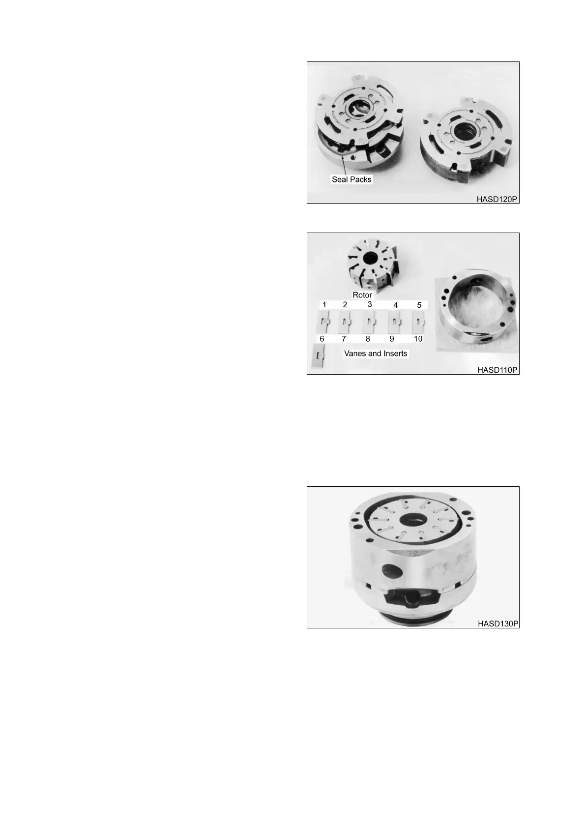
flat surface. Install seal packs into cavities
with seal retainer surface up and O-rings
facing downward into cavities.
3. Place a flex side over each of the support
plates with bronze wear surface facing up.
Align scribe marks to make sure that
correct flex side plate is used with correct
support plate.
NOTE:
Flex side plates develop a wear
pattern with rotor and vanes,
and should not be
interchanged.
4. For right-hand rotation units, set rotor on
flat wooden board with arrow pointing
right. For left-hand rotation units, set rotor
on flat wooden board with arrow pointing
left. Assemble the vanes and insert into
rotor in reverse order of removal. Make
sure that sharp chamfer edge of each
vane leads in direction of rotation. All
vanes must move freely in rotor slots with
no evidence of bind.
5. Assemble cam ring over rotor and vanes
with arrow pointing in the same direction
direction as rotor arrow. Lubricate top
surface of rotor and vanes liberally with
hydraulic oil.
6. Locate scribe mark on cam ring, outlet
support plate, and flex side plate. Hold the
outlet support plate and flex side plate
together and assembly over the cam ring
and rotor with scribe marks in line.
7. Hold cartridge together to prevent
movement and the assembly along with
the wooden board over so outlet support
plate rests on a flat surface, and the board
is up. Remove the board.
Figure 16
Figure 17
Figure 18