S0708470K
Page 21
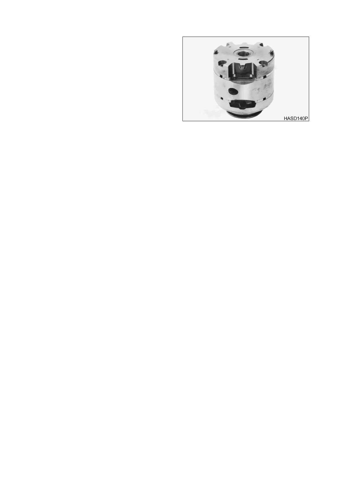
Steering and Brake Pump (Denison T67DB Series)
8. Lubricate the exposed surface of rotor and
vanes with hydraulic oil. Locate the scribe
mark on the inlet support plate and flex
side plate. Hold inlet support and flex side
plate together and assemble over cam ring
and rotor with scribe mark in line.
NOTE:
The cast-in arrows next to
socket head screws, indicate
cartridge of rotation.
9. Thread the two socket head screws into
cartridge until snug (hand tight).
10. The O.D. of all component parts of the
cartridge kit must be in line with each other
or cover cannot be installed. Align the
cartridge as follows:
11. Install cover over the cartridge. Tap lightly on cover with your hand until each part centers. Remove
the cover gently so as not to disturb alignment. Torque socket head screws to the torque noted below,
and recheck kit alignment with cover. Repeat until cartridge is aligned.
NOTE:
Center End Cartridge Kit Torque: 2 - 3 Nm (25 - 35 in lb)
NOTE:
Shaft End Cartridge Kit Torque: 11 Nm (100 in lb)
12. Check rotor for bind by inserting index finger through shaft opening of inlet support plate. Hold the
cartridge kit in a horizontal shaft position and lift rotor with your finger, The rotor should move freely
back and forth within the cartridge. If the rotor binds, open kit, clean and stone all possible areas of
bind, then reassemble the cartridge kit using aforementioned procedure. The rotor
MUST
move
freely within cartridge when assembled.
Figure 19