AV7000 LINEAR CAMERA REFERENCE MANUAL
Leveling the RangeFinder
Before beginning normal operations, the RangeFinder must be level with the conveyor
surface. This is especially important to dimensioning applications.
WARNING: The RangeFinder uses visible red
lasers and is rated as a Class 2 Laser Product. Do
not look directly into the beam.
Prerequisites:
RangeFinder software revision 9.0 (or greater)
RangeFinder power must be ON during this procedure.
Confirm correct mounting location based on application drawings
Tools Required:
Socket Driver (13mm)
To level the RangeFinder:
1. Make sure the T-bolts holding the RangeFinder Brackets to the mounting structure are
only finger-tight (4 places).
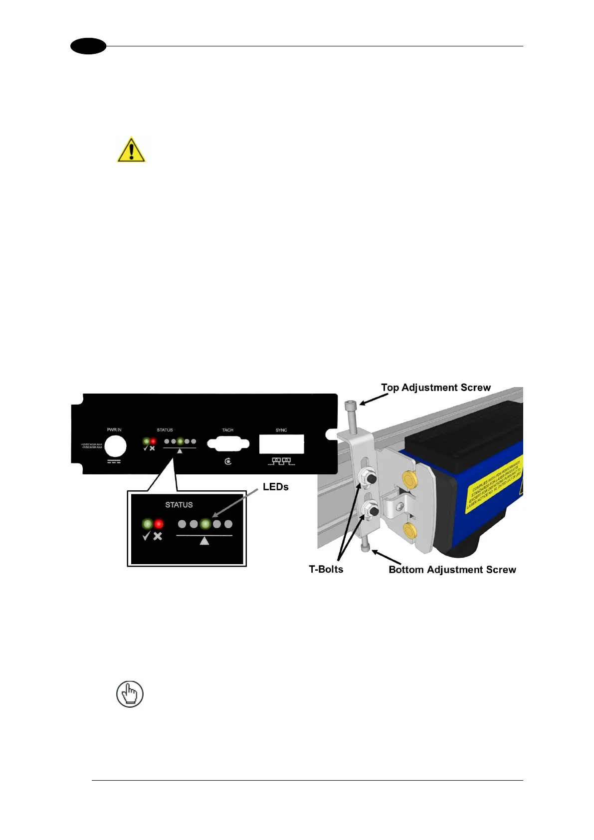
Figure 107: RangeFinder Leveling
2. Check the five leveling LEDs on the bottom panel of the RangeFinder. The lit LED is like
the bubble on a standard level. If the center LED is lit, no adjustment is needed.
3. If one of the LEDs is lit to the left or right of center, make adjustments to the top and
bottom adjustment screws on both sides of the RangeFinder until the center LED is lit.
NOTE: The leveling screws can be finger adjusted,
and don’t require an Allen wrench. Once the
RangeFinder is leveled, the mounting bolts hold it in
place.
4. Once level, tighten the mounting hardware (T-bolts).

 Loading...

