101 |
ETAS ES800 System | User Guide
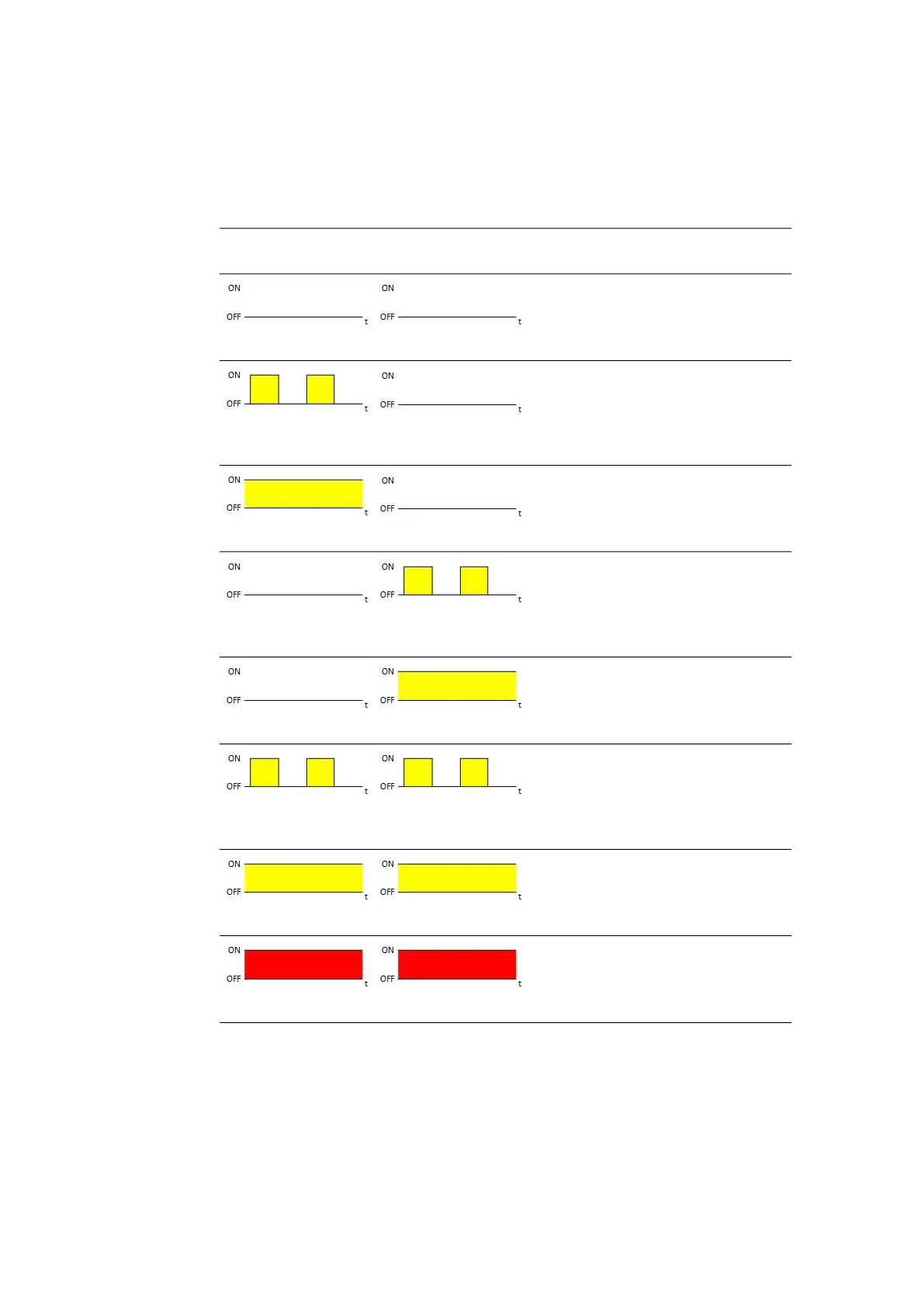
12.6.5 Display of the Function State of the FlexRay Interface
Each FlexRay channel is assigned an LED to indicate the function state of the Flex-
Ray node (LEDs CAN4/FLX1 and CAN5/FLX2). In the activated state of the module,
the LEDs assigned to the connections show the following function states:
LED
CAN4/FLX1
LED
CAN5/FLX2
State
Off
Off
FlexRay node inactive,
FlexRay controller not configured
Flashing yellow,
0.5 s on/0.5 s off
Off
FlexRay channel A active,
waiting for synchronization
Illuminated yellow
Off
FlexRay channel A active,
synchronized, ready for data
exchange
Off
Flashing yellow,
0.5 s on/0.5 s off
FlexRay channel B active,
waiting for synchronization
Off
Illuminated yellow
FlexRay channel B active,
synchronized, ready for data
exchange
Flashing yellow,
0.5 s on/0.5 s off
Flashing yellow,
0.5 s on/0.5 s off
FlexRay node active (channel A and
channel B), waiting for synchroniza-
tion
Illuminated yellow
Illuminated yellow
FlexRay node active (channel A and
channel B), synchronized, ready for
data exchange
Off
Off
Error