103 |
ETAS ES800 System | User Guide
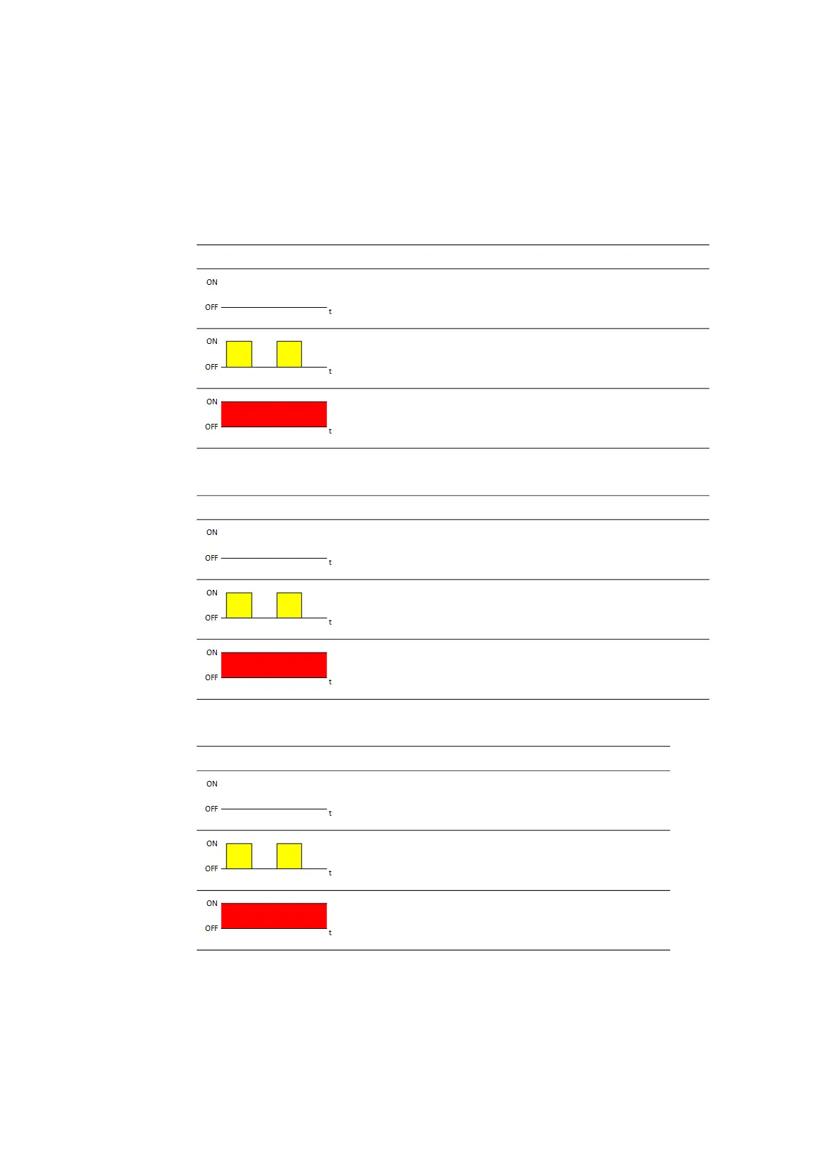
12.7.7 Display of Function State of CAN Interface
In the switched-on state of the module, the LEDs assigned to the connections
CAN and CAN / FLX of the ES891.x module show the following function states in the
CAN operating mode:
CAN4/FLX1 Interface (CAN Operating Mode)
CAN5/FLX2 Interface (CAN Operating Mode)
CAN3 Interface
LED CAN4 / FLX1 Description State
Off Communication at the CAN4 interface
interrupted
Flashing yellow,
0.5 s on/0.5 s off
Communication at the CAN4 interface
Illuminated red Error
LED CAN5 / FLX2 Description State
Off Communication at the CAN5 interface
interrupted
Flashing yellow,
0.5 s on/0.5 s off
Communication at the CAN5 interface
Illuminated red Error
LED CAN3 Description State
Off Communication at the CAN3
interface interrupted
Flashing yellow,
0.5 s on/0.5 s off
Communication at the CAN3
interface
Illuminated red Error