71 | Functions of the System
ETAS ES800 System | User Guide
11 Functions of the System
This chapter contains information about the following topics:
• LED Displays of the System. . . . . . . . . . . . . . . . . . . . . . . . . . . . . . . . . . . . . . . . . . . . . . . 71
• Operating States. . . . . . . . . . . . . . . . . . . . . . . . . . . . . . . . . . . . . . . . . . . . . . . . . . . . . . . . . 77
• "Wake-Up" Function. . . . . . . . . . . . . . . . . . . . . . . . . . . . . . . . . . . . . . . . . . . . . . . . . . . . . . 79
• Changing between Operating States. . . . . . . . . . . . . . . . . . . . . . . . . . . . . . . . . . . . . 80
• Synchronization of the ES800 System . . . . . . . . . . . . . . . . . . . . . . . . . . . . . . . . . . . 82
• Configuring the Modules (Web Interface) . . . . . . . . . . . . . . . . . . . . . . . . . . . . . . . . 83
• Updating the Firmware . . . . . . . . . . . . . . . . . . . . . . . . . . . . . . . . . . . . . . . . . . . . . . . . . . . 86
• Software Integration . . . . . . . . . . . . . . . . . . . . . . . . . . . . . . . . . . . . . . . . . . . . . . . . . . . . . 87
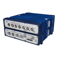
11.1 LED Displays of the System
Every module of the ES800 system is equipped with LEDs to indicate the operating
and function state of the module as well as with LEDs to indicate the function of
individual interfaces.
11.1.1 Display during Booting
While the ES800 modules are booting, the LEDs are tested with different flashing
sequences one after the other. The test lasts approximately 15 seconds.
11.1.2 Display of the Operating State (All Modules)
On the left of the front side of each module features four LEDs for indicating the
operating, error and synchronization state of the module or module stack:
- ON: Power supply and operating mode
- ERR: Error states or firmware update of the module
- TEMP: Temperature inside the housing
- SYNC: Synchronization state and synchronization function (master or
slave)