218 |
ETAS ES800 System | User Guide
17.10.2 Cable AS_CBV822.2
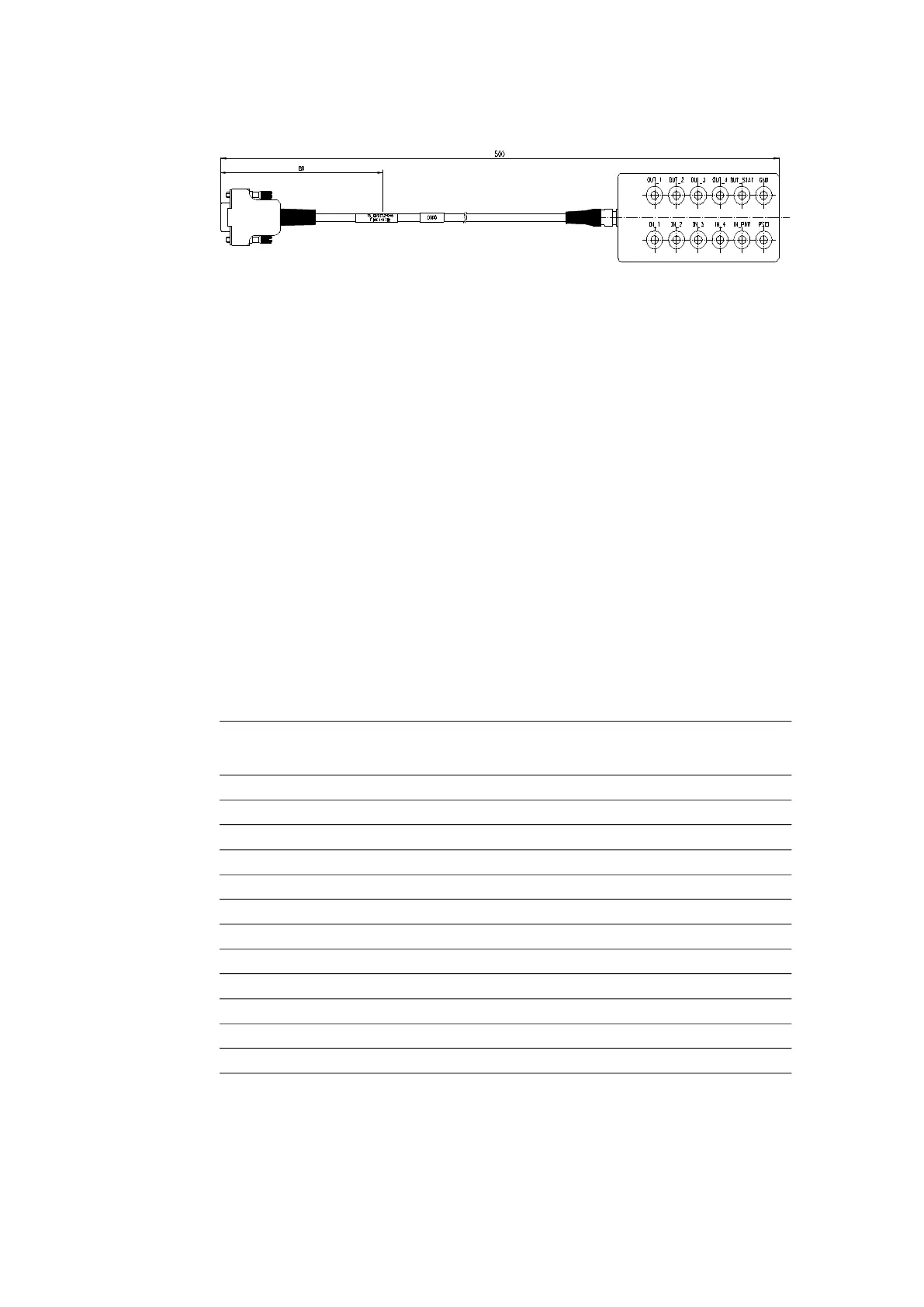
Fig. 17-36 Cable AS_CBV822.2
Usage
Cable for connecting the I/O interface of the ES820.1 Drive Recorder or the ES830.1
Rapid Prototyping Module via a breakout box with laboratory sockets. The follow
-
ing sockets are provided:
- Inputs:
• IN1 to IN4
• IN_POWER_BUTTON
• Power Status Coordination Input (PSCI)
- Outputs:
• OUT1 to OUT4
• OUT_STATUS
- Other:
• Ground of the ES820.1/ ES830.1 modules
Assignment of I/O Signal and Laboratory Sockets
The signals of the I/O interface are assigned to the following laboratory sockets:
Temperature Range
-40 °C to +85 °C/ -40 °F to +185 °F
I/O Interface Designation of the laboratory
sockets
Pin Signal
1 OUT_1 OUT_1
2 OUT_2 OUT_2
3 OUT_3 OUT_3
4 OUT_4 OUT_4
9 OUT_STATUS OUT_STAT
11 IN_POWER_BUTTON IN_PWR
12 PSCI PSCI
13 IN_1 IN_1
14 IN_2 IN_2
15 IN_3 IN_3
16 IN_4 IN_4
17 GND GND


 To Next Page