67 | ES891.x ECU and Bus Interface Module
ETAS ES800 System | User Guide
9.4 Function Groups
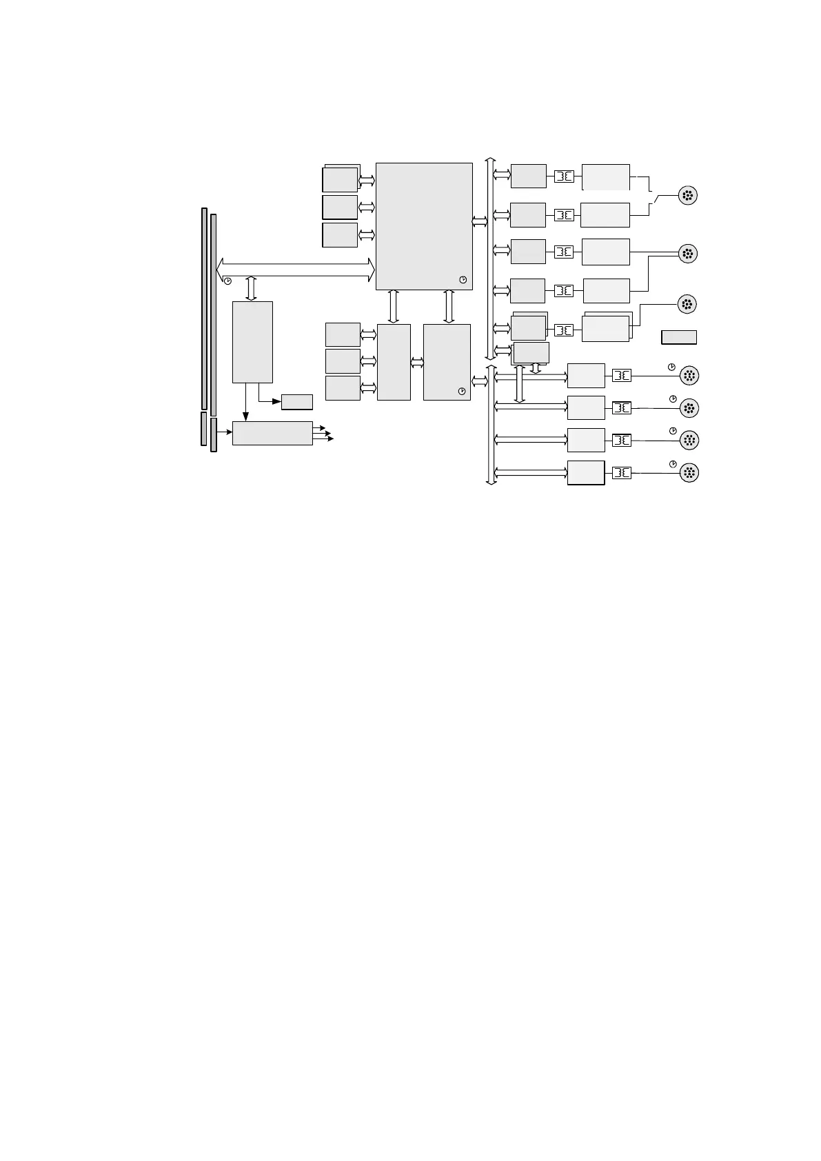
Fig. 9-3 ES891.x Function Groups
9.4.1 Ethernet Switch
In addition to the Ethernet connection in the system connector of the stack (see
chapter
3.3 on page 24), the Ethernet switch of the module provides interfaces for
the connection of further modules:
- a HOST Ethernet interface (see chapter 12.1 on page 89)
- an FE Fast Ethernet interface (see chapter 12.2 on page 90)
- two GE FETK/Gigabit Ethernet interfaces (see chapter 12.4 on page 92)
9.4.2 Interfaces to the Vehicle Bus
The interfaces to the vehicle bus are available in different combinations:
- five CAN / CAN FD interfaces (see chapter 12.7 on page 102)
- one LIN interface (see chapter 12.8 on page 105)
- one FlexRay interface (see chapter 12.6 on page 100)
9.4.3 Other Function Groups
- Power supply (see chapter 3.4 on page 24)
- Function groups for power-saving functions ("Wake-Up", see chapter 11.3
on page 79)
2XDDR3
256 MB
CAN
Controller
CANTransceiver
CAN/FLX
FLEXRAY
Transceiver
FLEXRAY
Controller
CAN
Controller
/
2
/
2
InterfaceHub
CPU
CAN
CAN
Controller
CAN/CAN‐FD
Transceiver
/
2
FE
Ethernet
Transceiver
10/100
PC
Ethernet
Transceiver
10/100/1000
SRAM
36Mbit
FLASH
16Mbit
DDR3
256MB
DDR3
256MB
FRAM
32KB
LED‘s
Board
Management:
PowerSupply
Control
Thermal
Control
FANDrive
CAN/LIN
LIN
Transceiver
LIN
Controller
CAN
Controller
Up‐ /Down‐
System
Connector
FLASH
64M B
SystemBus:Highspeeddata,Trigger,Sync,Management
PowerSupply
Ethernet
Transceiver
10/100 /1000
GE/FETK
GE/FETK
Ethernet
Transceiver
10/100/1000
CAN/CAN‐FD
Transceiver
CAN/CAN‐FD
Transceiver
Ethernet
Switch
Sync
Sync
Sync
Sync
Sync
Sync
Sync
FETK
FETK