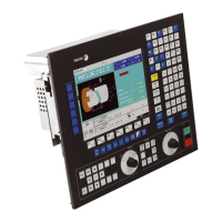
Operating manual
CNC 8055
CNC 8055i
EXECUTE / SIMULATE
4.
·T· MODEL
SOFT: V02.2X
·63·
Display
4.2 Display
With this option, it is possible to select the most appropriate display mode at any time even during
execution or simulation of a part program.
The display modes available at the CNC and which can be selected with softkeys are:
• STANDARD display mode.
• POSITION display mode.
• PART-PROGRAM display.
• SUBROUTINES display mode.
• FOLLOWING ERROR display mode.
• USER display mode.
• EXECUTION TIME display mode.
All the display modes have a window at the bottom of the CRT which shows the history with the
conditions in which machining is being done. The information shown is as follows:
F and % Programmed feedrate (F) and selected feedrate override %. When feed-hold is
active, the feedrate value is shown in reverse video (highlighted).
S and % Programmed spindle speed (S) and override % of the selected spindle speed.
T Number of active tool.
D Number of active tool offset.
S RPM Real spindle speed. It is given in rpm.
When working in M19 this indicates the position of the spindle. It is given in
degrees.
S M/MIN Real spindle speed. It is given in meters per minute.
G All displayable G functions that are active.
M All displayable M functions that are selected.
PARTC Parts counter. It indicates the number of consecutive parts executed with the
same part-program.
Every time a new program is selected, this variable is reset to "0".
With this CNC variable "PARTC" it is possible to modify this counter from the PLC,
from the CNC program and via DNC.
CYTIME Indicates the time elapsed while executing the part. It is given in "hours : minutes
: seconds : hundredths of a second" format.
Every time a part-program execution starts, even when repetitive, this variable is
reset to "0".
TIMER Indicates the count of the timer enabled by PLC. It is given in "hours : minutes :
seconds" format.

 Loading...