Operating manual
CNC 8055
CNC 8055i
EXECUTE / SIMULATE
4.
·T· MODEL
SOFT: V02.2X
·83·
Graphics
4.5.7 Measurement
To use this function, a line graphics (planes XZ, XC or ZC) must be selected and the CNC must not
be executing or simulating the part-program. If this is the case, it must be interrupted.
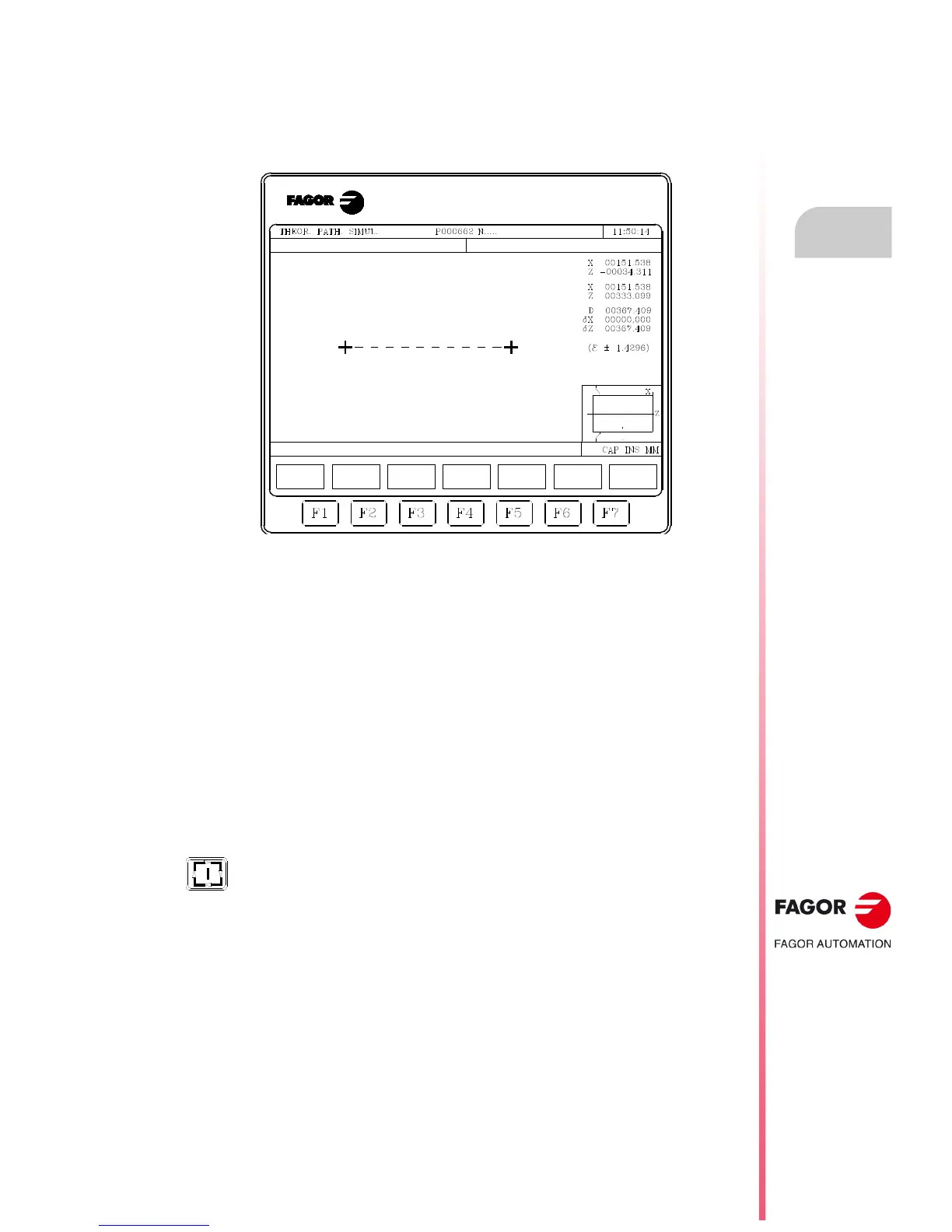
Once this function is selected, the CNC shows the following information on the screen:
The center of the CRT shows a dotted line with two cursors, the section to be measured. Also, the
right-hand side of the screen shows:
• The coordinates of those two cursors with respect to part-zero.
• The distance "D" between them and the components of this distance along the axes of the
selected plane "X" and "Z".
• The cursor step "" corresponding to the selected display area. It is given in the work units,
millimeters or inches.
The CNC shows the selected cursor and its coordinates in red.
To select the other cursor, press the [+] or [-] key. The CNC shows the new selected cursor and its
coordinates in red.
Use the [] [] [] [] keys to move the selected cursor.
Likewise, the cursor may be moved to the indicated end using the keystroke combinations
[SHIFT]+[], [SHIFT]+[], [SHIFT]+[], [SHIFT]+[].
To quit this command and return to the graphics menu, press [ESC].
Also, if [START] is pressed, the CNC exits this work mode and returns to the graphics
menu.
 Loading...