Operating manual
CNC 8055
CNC 8055i
PLC
10.
·T· MODEL
SOFT: V02.2X
·187·
Logic analyzer
10.10 Logic analyzer
The logic analyzer is especially suited to help in the machine start-up and for troubleshooting errors
and critical situations in signal behavior.
This option is used to analyze the behavior of the logic PLC signals according to a time base and
certain trigger conditions set by the user.
Up to 8 signals can be analyzed at the same time. The results are shown using a graphic interface
that makes it easy to interpret the data.
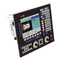
10.10.1 Description of the work screen
The screen for the logic analyzer is divided into the following areas or display windows:
1. Status window.
It graphically shows the status of each selected signal. It is divided into two areas: the variable
area and the status area.
The variables area shows the names or symbols of the logic signals to be analyzed.
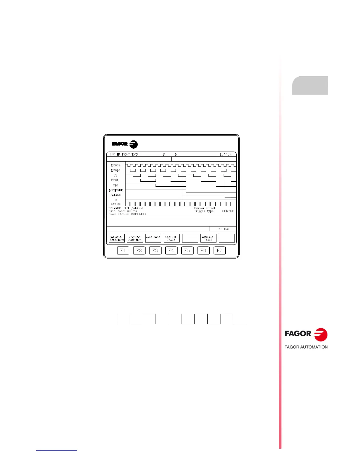
The status area shows the status of each variable in square waves. The line for logic level 0 is
shown with a thicker line.
Likewise, it shows a vertical red line to indicate the TRIGGER point and another green vertical
line to indicate the cursor position.
The vertical green line for the cursor may be moved along the trace and helps measure the time
between two points of the trace.
The status area is divided into several vertical stripes. Each stripe represents the amount of time
defined by the "time base" constant.
The "time base" constant sets the resolution of the logic signals and, after being set by the user,
may be modified as often as desired. The "time base" is inversely proportional to the resolution
of the signals; thus, the lower the "time base" the greater the signal resolution and vice versa.
2. Cycles window
This window shows several vertical lines "¦". Each one indicates the instant when the execution
of a new cycle of the PLC program starts.
It permits maintaining a relationship between the flux of the logic signals and the duration of each
PLC execution cycle.
 Loading...