Measuring
Adapting to the transducer
MGCplus A0534-30.0 HBM: public 163
12. In the Decimal places edit field enter the desired number of decimal
places and confirm with
.
13. In the Step selection field select the desired step and confirm with
.
Information
The step refers to the last decimal place of the display value.
Example:
Entry 10.0 kW
Step 1 means display jumps every 0.1 kW
Step 5 means display jumps every 0.5 kW
Entry 10.000 kW
Step 1 means display jumps every 0.001 kW
Step 5 means display jumps every 0.005 kW
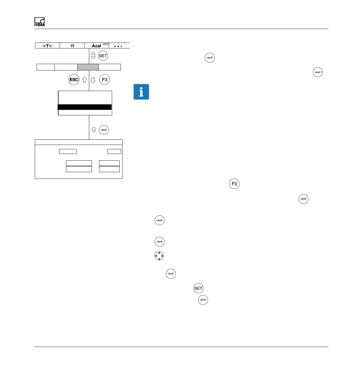
14. Go back to the pull-up menu with
.
15. In the pull-up menu select Analog outputs and confirm with
.
16. In the Output Vo1 selection field select the desired signal and confirm
with
.
17. In the Output Vo2 selection field select the desired signal and confirm
with .
18. Use
to select the Output characteristics pt.2 edit field and enter
the desired value 5 (left for the display, right for the analog output). Con
firm with .
19. Use the Switch key
to go to measuring mode and confirm the con
firmation prompt with
.
Output Vo1: Output Vo2:
Output characteristics ppm V
Pt.1:
Pt.2:
ANALOG OUTPUTS CHANNEL1
0.0000 ...
Gross Net
0.0000 ...
100.0000 ... 0.0000 ...
AmplifierSystem Display Options
Transducer
Signal conditioning
Display
Analog outputs
Switch