Introduction
System description
MGCplus A0534-30.0 HBM: public 19
3.3 System description
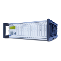
The MGCplus system is structured modularly. Depending on the housing
variant, up to 16 slots are available for single and multi-channel amplifier
modules. Thus up to 128 measuring points can be measured in an
MGCplus.
Each amplifier module works independently through its own CPU. Data
preparation, for example taring, filtering and measuring range adjustment, is
carried out digitally. This eliminates the disadvantages of analog data prepa
ration, such as time and temperature-dependent drift, errors due to compo
nent tolerances, greatly limited flexibility and extensive circuitry. An essen
tial precondition for this is analog/digital conversion with no loss of
information. The digitally conditioned signal is directed to the internal bus.
For single-channel modules, two analog outputs (voltage) are available in
addition to the digital measured values.
An internal standard PC computer in credit-card format collects data with a
total sampling rate of up to 307,200 measured values per second (4-byte
integer format: 3-byte measured value + 1-byte status). All measurement
signals can be acquired in parallel, since each channel has its own ADU. No
Sample & Hold or Multiplexer is used in the MGCplus. This ensures continu
ous digital filtering and maximum signal stability.
Data is sent to an external computer or PLC via interfaces such as Ethernet.
A large part of the system functionality is implemented by device-internal
software (also called firmware). We therefore recommend you use our free
firmware updates and always keep your devices updated to the latest
firmware version. For further information go to www.hbm.com/downloads.