Connection
Inputs and outputs, remote controls
88 A0534-30.0 HBM: public MGCplus
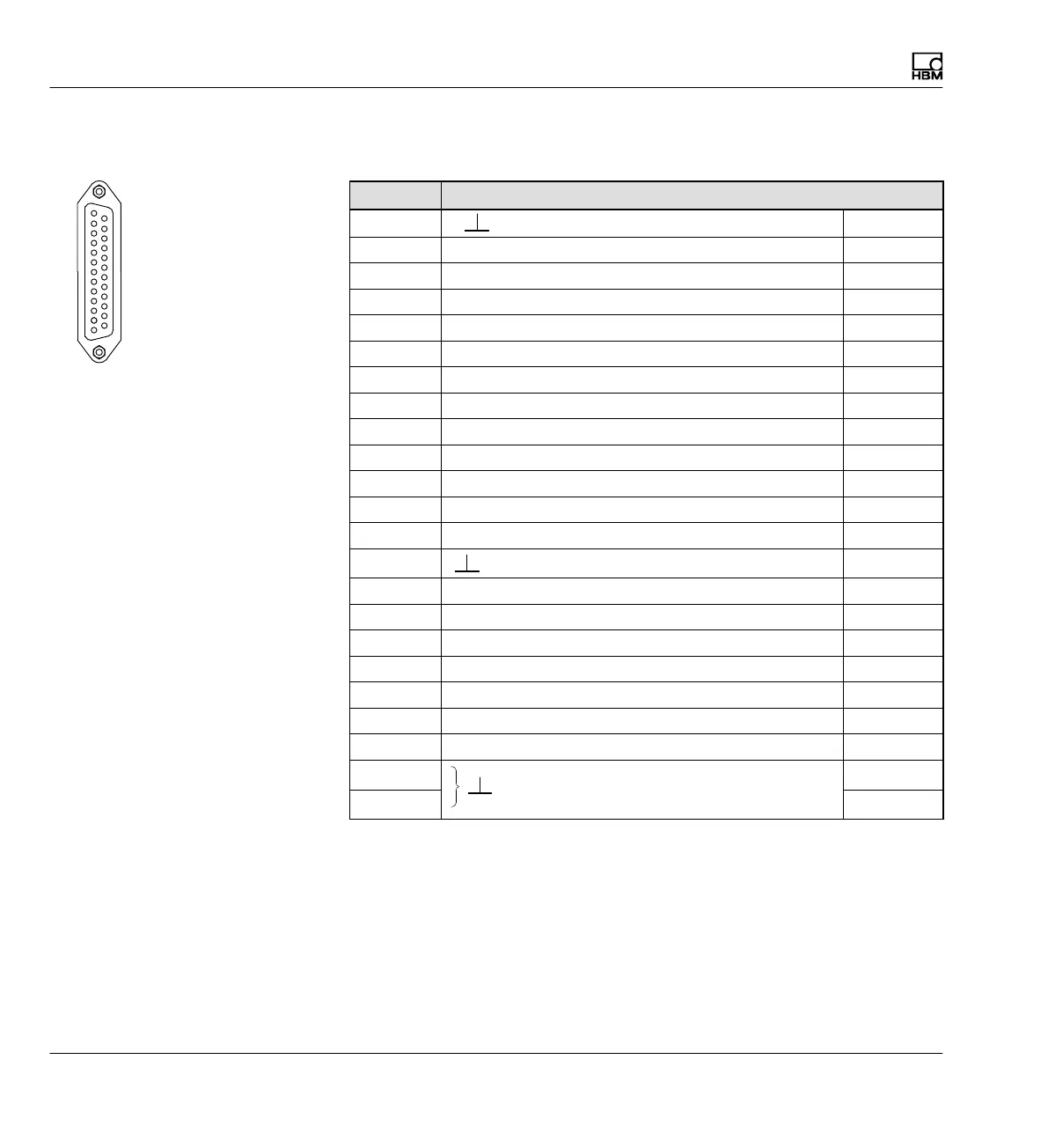
4.5.3.1 Socket assignment AP01i/AP03i/AP14/AP17
Pin Function
1
Digital
2 Remote control 1 Input
3 Remote control 2 Input
4 Remote control 3 Input
5 Remote control 4 Input
6 Remote control 5 Input
7 Remote control 6 Input
8 Remote control 7 Input
9 Remote control 8 Input
10 no function -
11 no function -
12 V
O2
(Ra>5k) Output
13 V
O1
(Ra>5k) Output
16
Digital
Input
17 Limit value output 1 Output
18 Limit value output 2 Output
19 Limit value output 3 Output
20 Limit value output 4 Output
21 Warning Output
22 no function -
23 no function -
24
to Pin 12
to Pin 13
Analog
25
Tab. 4.1 Sct2
Assignment of outputs
Analog outputs
S On pin 12 the analog output signal V
O2
is present.
The connected load resistor must be greater than 5 kohms.
Sct 2
1
13
14
25
Outputs
OUTPUT