Display
Display format
216 A0534-30.0 HBM: public MGCplus
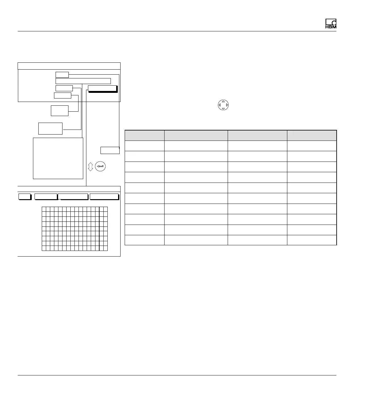
9.1.3 Setup window components
Image no.:
You can enter the numbers 1...9 in this edit field. This allows you to save
your current display settings as a number or call up factory default settings.
You can also define the order in which the image types are selected in mea
suring mode with the cursor keys
.
The following order is defined in the factory setting:
Image no.: Image type: Channels/signals Status line
0 1 measured value All One
1 3 measured values All -
2 6 measured values All -
3 t‐y realization All -
4 x‐y realization All -
5 Limit value status - -
6 Recording status - -
7 Free - -
8 Free - -
9 Free - -
Image type
With this image type you define the number of measurement signals that
can be realized simultaneously (for numeric values only) or the type of real
ization (graph only). You can also display the status of the four selected limit
switches.
Channel
Gross
Net
PV1
PV2
PV12
LV1
LV2
LV3
LV4
All signals
10 1112131415161
2
3
4
5
6
7
8
9
OK Cancel All channels
CHANNEL/SIGNAL SELECTION
0...9
Channels/signals:
0 ...
One measured value
All
Image no.:
Image type:
define...
DISPLAY FORMAT One measured value
Free
One measured value
3 measured values
6 measured values
YT realization
XY realization
Limit val. status
Recording status
All
Selection
Status line
Off
Off
On