Measuring
Adapting to the transducer
MGCplus A0534-30.0 HBM: public 175
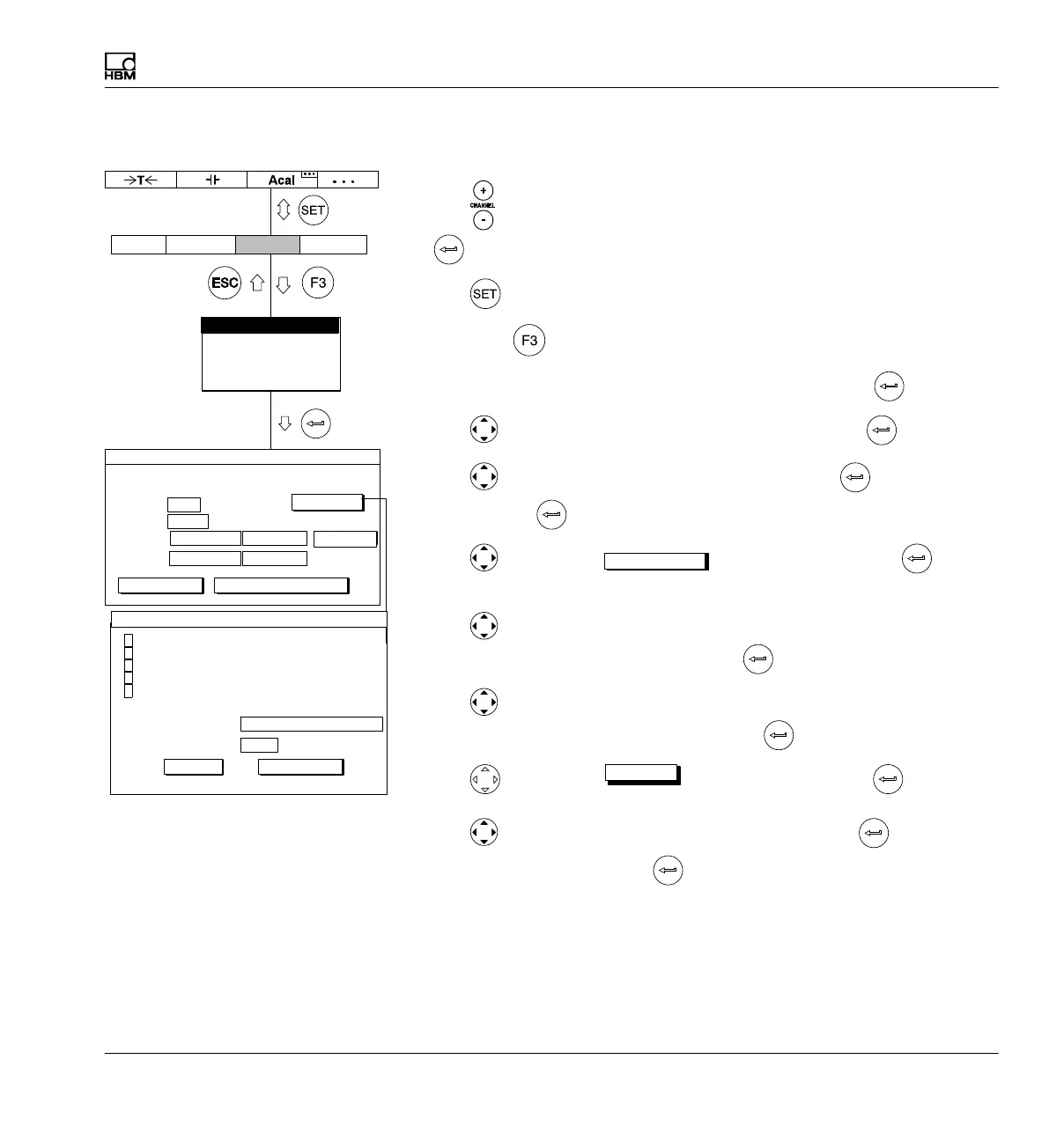
7.3.11.1 Direct entry of transducer characteristics
1. Use
or a direct entry to choose the desired channel (for example 3.2
).
2. Use
to switch to Setup mode.
3. Press the
function key.
4. In the pull-up menu select Transducer and confirm with
.
5. Use
to select type Pulse counter and confirm with .
6. Use
to switch to the Level selection field, press and select 5V.
Confirm with
.
7. Use
to select the
Ext. fct. ...
button and confirm with (for
explanations of extended functions).
è see page 180)
8. Use
to select the activation fields Frequency quadrupling and An
alyze F2 signal and activate them with
.
9. Use
to switch to the Switch output LV1 selection field, select F1
Counting signal to LV1 and confirm with
.
10. Use
to select the
OK
button and confirm with .
11. Use
to switch to the Unit selection field and press . Select deg
as the unit and confirm with
.
12. In both the Zero point edit fields enter the value 0.
13. In the left edit field Nominal (rated) value enter the value 360.
14. In the right edit field Nominal (rated) value enter the value 0.180.
Switch output LV1:
Switch output LV2:
Ext.fct...Ext.fct...
AmplifierSystem Display Options
Transducer
Signal conditioning
Display
Analog outputs
Switch
0.1800 ...
Type: Freq.0..20kHz
Level:
Unit: kImp
Zero pt.:
Nom. val.:
TRANSDUCER CHANNEL1
deg
0.0000 ... 0.0000 ...
360.0000 ...
calibrate... Adjust amplifier
5V
measure
Enhanced functions
F1 counting signal to LV1
OK
Glitch filter (min. pulse width 1.6s)
Frequency quadrupling
Analyze F2 signal
Zero index input active
Transducer error input active
Off
Cancel