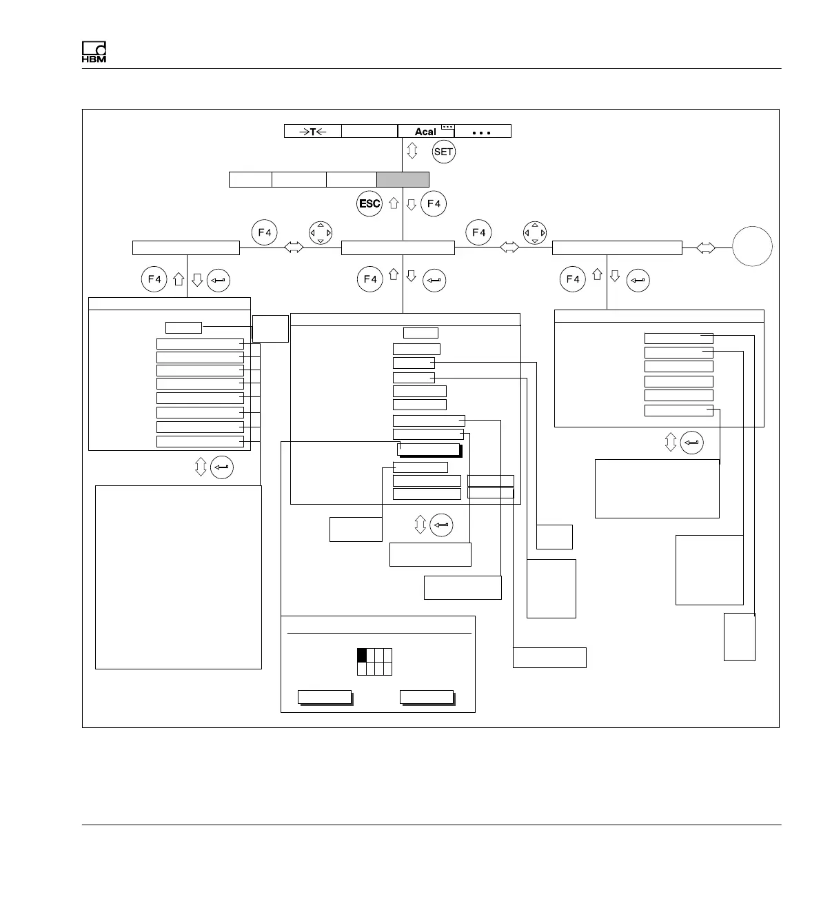
Menu structure
MGCplus A0534-30.0 HBM: public 297
Limit value output:
Combination:
Input signal 1:
Input signal 2:
Input signal 3:
Input signal 4:
LIMIT VALUE COMBINATION CHANNEL 1
Limit value 1
Limit value 2
Limit value 3
Limit value 4
−−−
AND
Remote control
Input 1
Input 2
Input 3
Input 4
Input 5
Input 6
Input 7
Input 8
Not assigned
Control inputs Channel 1
Not assigned
Not assigned
Not assigned
Not assigned
Not assigned
Not assigned
Not assigned
1 ....
1-LV1 ...
No
100.000 ...
Gross
Limit switch
Name
Enable
Input signal
Level
Hysteresis
Direction
Output logic
1.000 ...
Exceed
Limit switch 1 Channel 1
Positive logic
Input
Message when On
Message when Off
1-LV1 ON...
1-LV1 OFF...
Normal
Normal
Free
%
%
No
Yes
Gross
Net
PV1
PV2
PV12
Not assigned
ACAL−autocal
TARA−tare
Delete CPV1−PV1
HLD1−hold memory1
Delete CPV2−PV2
HLD2−hold memory2
ZERO−Zero balance
SHNT−Shunt On/Off
CAL input: Calibration signal
ZERO input Zero signal
INV sign reversal
PSEL1−P−set coding line 1
PSEL2−P−set coding line 2
PSEL4−P−set coding line 4
REMT−Remote control On/Off
INT−Start/stop integration
or
AmplifierSystem OptionsDisplay
or
−−−−
Limit value 4
Limit value 4 inverted
Control input 4
Control input 4 inverted
−−−
1
2
3
4
AND
OR
EXOR
NAND
NOR
NEXOR
Exceed
Undershoot
Normal
Reverse video
Control inputs Limit switch Limit value combination
Enabled
Disabled
Positive logic
Negative logic
Delay
define...
Limit value delay time
Limit value On
Limit value Off
12 3 4
Delay time
0ms
OKOK OKCancel
G
On
On
Off