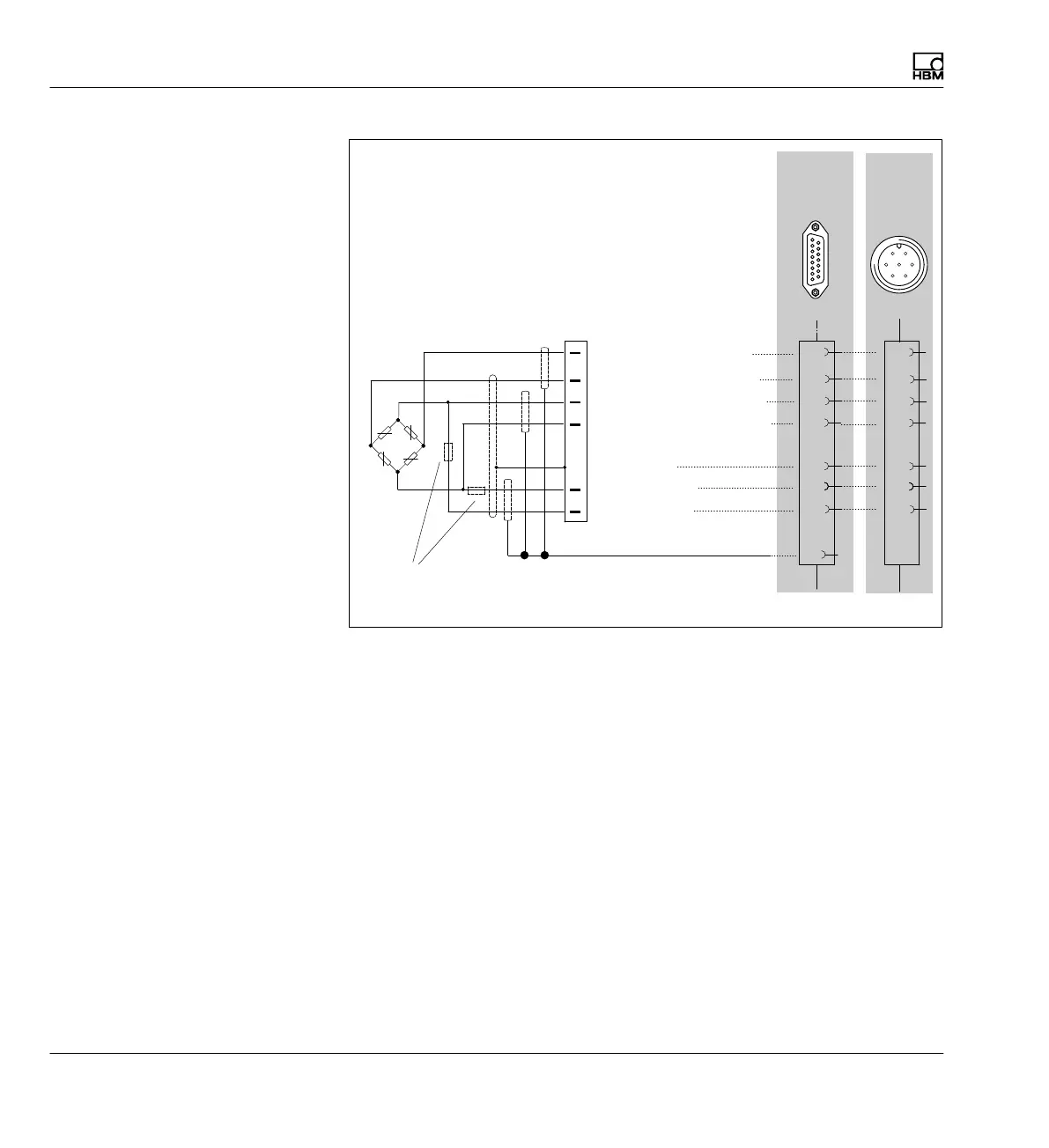
Connection
Shielding design
38 A0534-30.0 HBM: public MGCplus
8
13
15
12
Measurement signal (+)
Bridge excitation voltage (+)
Sense lead (-)
Sense lead (+)
Bridge excitation voltage (-)
Measurement signal (-)
Cable shield
5
6
Hsg.
4
1
2
4
3
RB / 2 (on the transducer)
Hsg. = Housing
AP01i
AP14
AP455i
1
8
9
15
AP03i
G
D
E
B
F
C
A
B
F
A
G
C
D
Hsg.
HBM recommends this connection technique for measuring amplifiers
ML10B, ML30B, ML38B, ML55B and ML455 with connection boards
AP01i, AP03i, AP14 and AP455i with very small measuring ranges, in
environments especially subject to interference and when long cables
are used.
This applies to all bridge connections.
With cable lengths >50 m, a resistor with half the value of the bridge
resistance (R_B/2) must be connected in each sense lead of the trans
ducer.