D1-N Series Servo Drive User Manual Servo Drive Configuration
HIWIN MIKROSYSTEM Corp. 5-35
Step
Figure Description
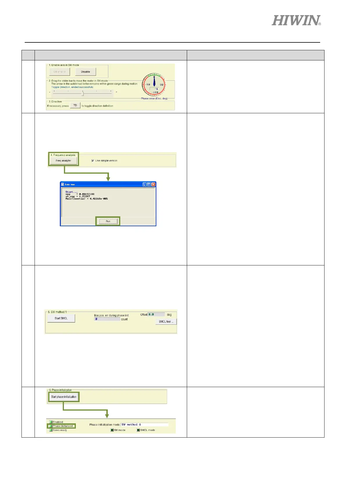
3
Check the definition of motion direction:
If the moving direction is inconsistent with what the
users have defined as forward or reverse direction,
click on TD
button to reverse the definition of
motion direction. After the message “Toggle
Direction, ended successfully” a
step 2 and proceed again.
4
Auto tuning:
Select Use simple version and click on Freq
analyzer button to show Auto tune window. Click
on Run button to analyze frequency response and
calculate parameters.
This function can be used to easily set system loop
gain. But in the following
cases, the calculated
parameter values may not be appropriate for the
system.
(1) The stiffness of the mechanism is too low.
(2) The backlash of the mechanism is too large.
(3) The load has been changed.
(4) The load inertia ratio is over 20.
Note:
(1) If mechanical resonance occurs during execution,
stop inputting Hard
ware enable signal or press
F12 function key (Refer to section 6.1.3).
(2) Users are allowed to tune manually, please refer to
section 10.3. For description of parameters vpg
and st_vpg, please refer to sections
5
Adjusting phase initialization:
By using SW method 1, the motor
move for a small
distance to complete phase
initialization.
After tuning completes in step 4,
confirm the tuning result by the following steps.
Step 1: Click on Start SMCL
electrical angle.
Step 2: Observe the values in the fields of Offset
and Max. pos. err during phase init..
Offset
shows the result of finding
electrical angle and Max. pos. err during
phase init. shows the largest movement
during the process.
Step 3:
Repeat step 1 and 2 to observe if the
offset is within +/- 15 degrees.
Step 4: If offset is too large, click on SMCL tool…
button for advanced tuning.
6
Execute phase initialization:
Click on Start phase initialization button. After
Phase Initialized indicator
means phase initialization
drive is able to control the
closed-loop control.
 Loading...
