D1-N Series Servo Drive User Manual Servo Drive Configuration
5-48 HIWIN MIKROSYSTEM Corp.
(3) Logical value
The logical value of each output is displayed. The displayed value can be TRUE or FALSE.
(4) Invert output voltage
If needed, select Invert state to invert the polarity of output voltage. Please be noted the internal
logic value of the servo drive will not be affected.
(5) Output voltage
The voltage level of the output pin will be displayed for users to check if the signal received by the
controller is correct.
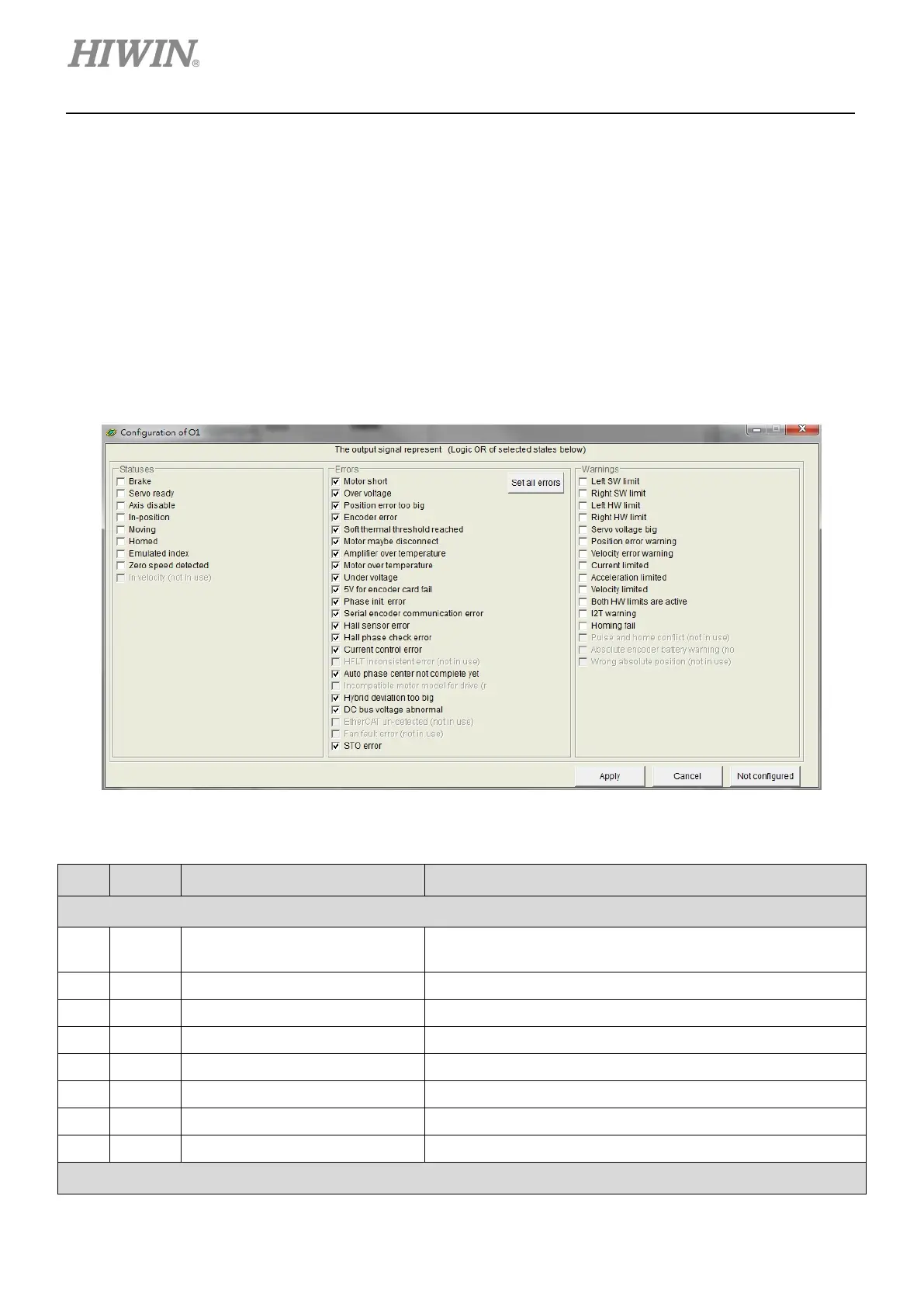
Figure 5.4.2.2
Table 5.4.2.1
Item Abbr. Output Function Description
Statuses
1 BRK Brake
Brake signal
If Brake is selected, other output functions cannot be set.
2 RDY Servo ready The motor is enabled.
3 DIS Axis disable The motor is disabled.
4 INP In-position In-position signal
5 MOV Moving The motor is moving.
6 HOMD Homed Homing completed.
7 EMI Emulated index Emulated Z-phase signal
8 ZSPD Zero speed detected Zero speed detection signal
Errors
 Loading...
