D1-N Series Servo Drive User Manual Specifications
HIWIN MIKROSYSTEM Corp. 2-7
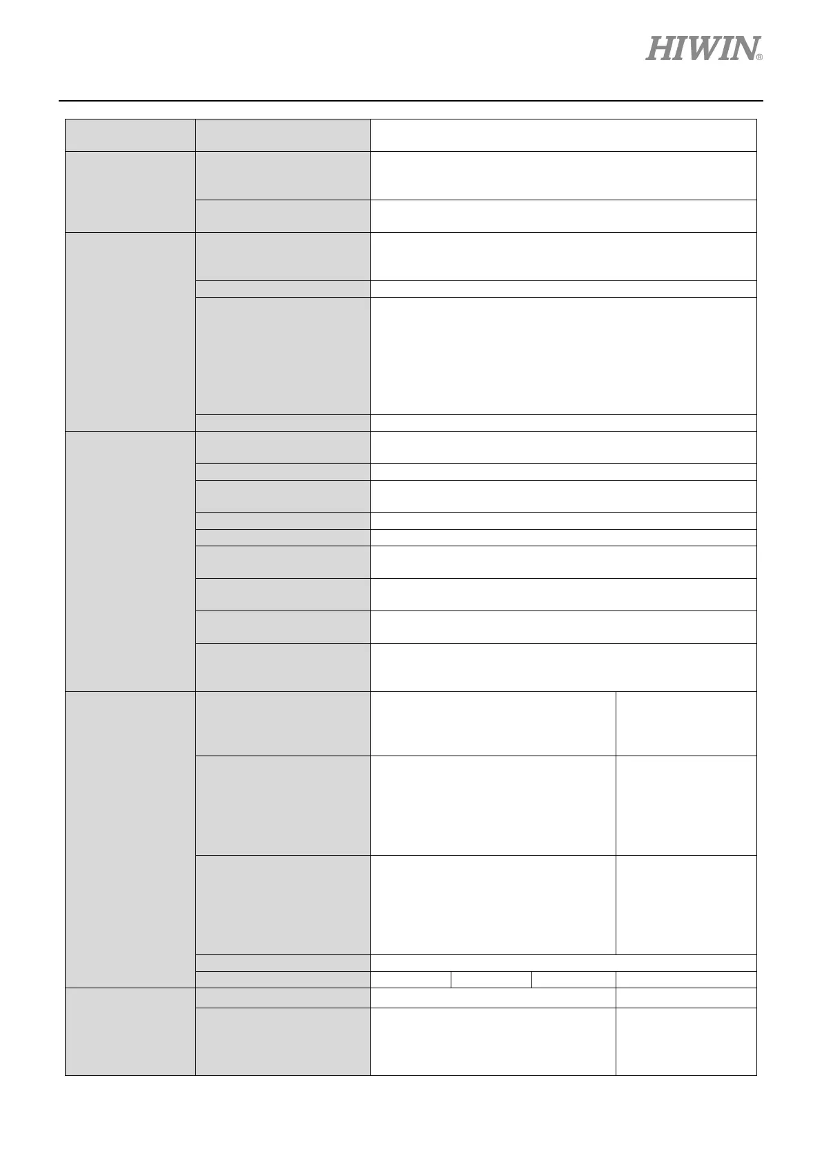
Communication Standard USB 2.0
Set servo drive parameters and monitor servo drive status
via computer.
Digital Input
Input
I1 ~ I10 input functions can be user-defined. (Optical coupler,
general-purpose input)
Input pin: 5 V/1 mA, 24 V/5 mA
Safety input
Two sets of safety inputs. The voltage for STO safety
function is 24 V. Signal interrupts > 6 ms
Digital Output
Output
O1 ~ O3 output functions can be user-defined. (Optical
coupler, general-purpose output)
PT Output
• PT+ and PT- signals are 3.3 V differential outputs.
• When the set position is reached, PT output is ON.
• Response time of digital encoder is below 0.1 us.
• Only supports digital AqB encoder
• PT pulse width: 25 ns ~ 100 us
• PT position accuracy: ±1 count (Up to 5,000,000
PDL Editor
Maximum Storage
for Codes
32 Kbytes
Supported Variable Type
Float: 32 bits
Integer: 16 and 32 bits (Array and pointer are supported.)
Four tasks can be run at the same time.
Control Commands for
Program Flow
Supports commands such as “if”, “else”, “while loop”, “for
loop”, “goto”, “till”, etc.
Operator
Includes arithmetic operators, logic operators and
comparison operators.
Task Synchronization
Supports lock and unlock commands to perform task
synchronization.
Length Limit for
User-defined Name
Label: 24 characters
Regenerative
Resistor
Resistance
Internal regenerative resistor 50
Ω/150 W (Note: When regenerative
energy is above 150 W, please install
regenerative resistor
is required.
Voltage Threshold for
Activation
+HV > 390 Vdc
(Input power: 230 Vac)
(Input power: 230
Vac)
• +HV > 735 Vdc
(Input power: 400
Voltage Threshold for
Deactivation
+HV < 380 Vdc
(Input power: 230 Vac)
(Input power: 230
Vac)
• +HV < 695 Vdc
(Input power: 400
Protection
Function
Undervoltage
+HV < 184 Vdc
(Input power: 230 Vac)
(Input power: 230
Vac)
 Loading...
