D1-N Series Servo Drive User Manual Specifications
2-8 HIWIN MIKROSYSTEM Corp.
o
o
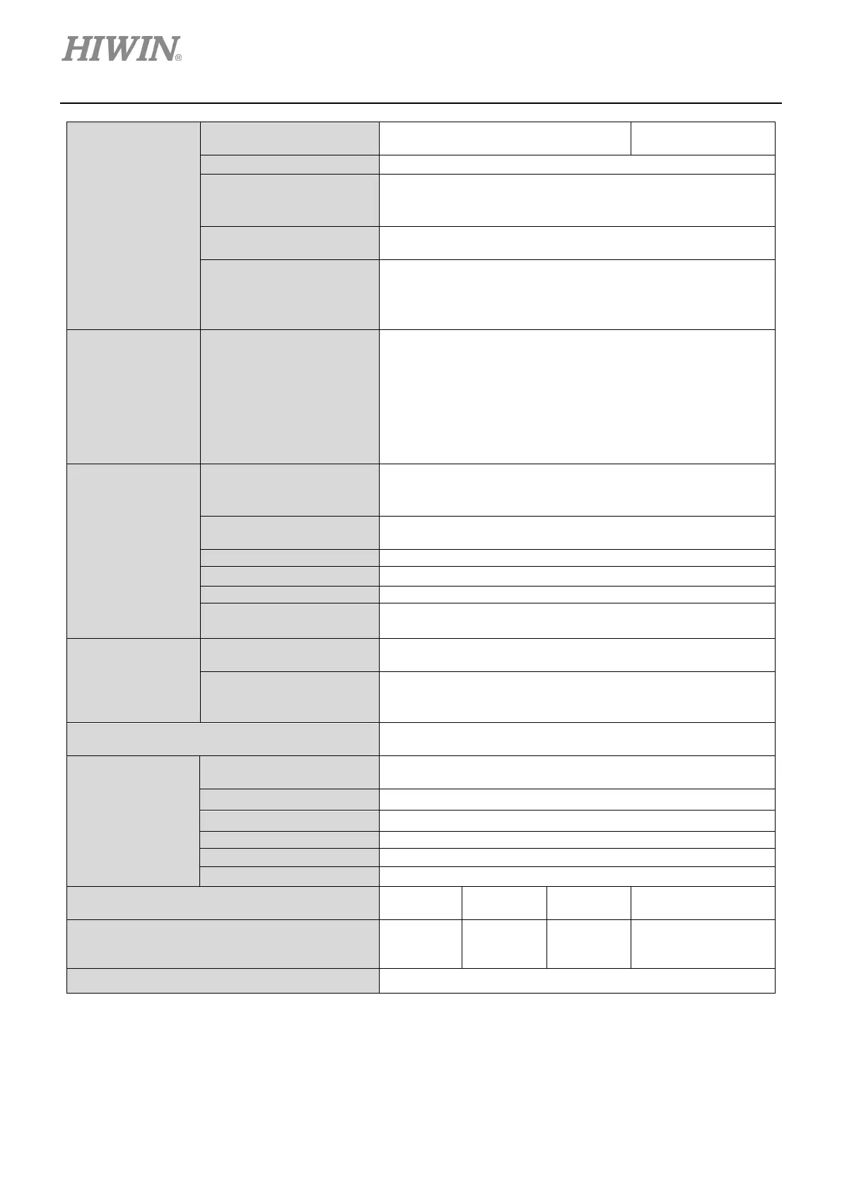
Short Circuit
• Short circuit between UVW wires
• Short circuit between UVW cable and ground (PE)
• Internal PWM bridge short circuit
Software Over
Temperature Protection
Starts to estimate temperature rise as continuous current is
exceeded.
Encoder Feedback Error
• The input voltage is 85% lower than normal voltage 5 V.
• Phase error (A/B phase)
• The signal of analog encoder is too weak.
Safety Function STO (Safe Torque Off)
• Two safety inputs are used to suspend motor current.
• STO status can be monitored via digital output.
• To disable safety function, X6-pin 20 and X6-pin 40
should be short-circuited.
• To enable safety function, the servo drive must be turned
off first. Connect safety inputs. X6-pin 20 and X6-pin 40
should not be short-circuited. After that, turn on the servo
Error
Compensation
Applicable Motor
• AC servo motor
Compensation Method
Creates error map to compensate encoder error by means of
linear interpolation.
Enabling Method
• Enabled after internal homing completes.
• Enabled by external input signal.
Communication
Module
EtherCAT
Connect to two RJ-45 connectors of X13.
Supports EtherCAT function (CoE or mega-ulink)
Modbus (RS485)
Connect to two RJ-11 connectors of X13.
• Supports serial communication with other servo drives.
• Supports Modbus RTU and ASCII protocols (Half duplex)
Frequency Suppression Range for Vibration
Suppression Filter (VSF)
0.1 Hz ~ 200 Hz
Environment
Operating Temperature
0 ~ 50
o
C (If temperature is above 55
o
C, forced ventilation
will be required.)
Storage Temperature -20
o
C ~ 65
o
C
0 to 90% RH (No condensation)
Weight (Accessory kit included) (kg)
Dimensions (Length x Width x Height)
75 mm x
75 mm x
101 mm x
272 mm x 119 mm x
254 mm
Case Complies with CE U.L. Spec 94 V-0 Flammability Rating
 Loading...
