D1-N Series Servo Drive User Manual Tuning
6-46 HIWIN MIKROSYSTEM Corp.
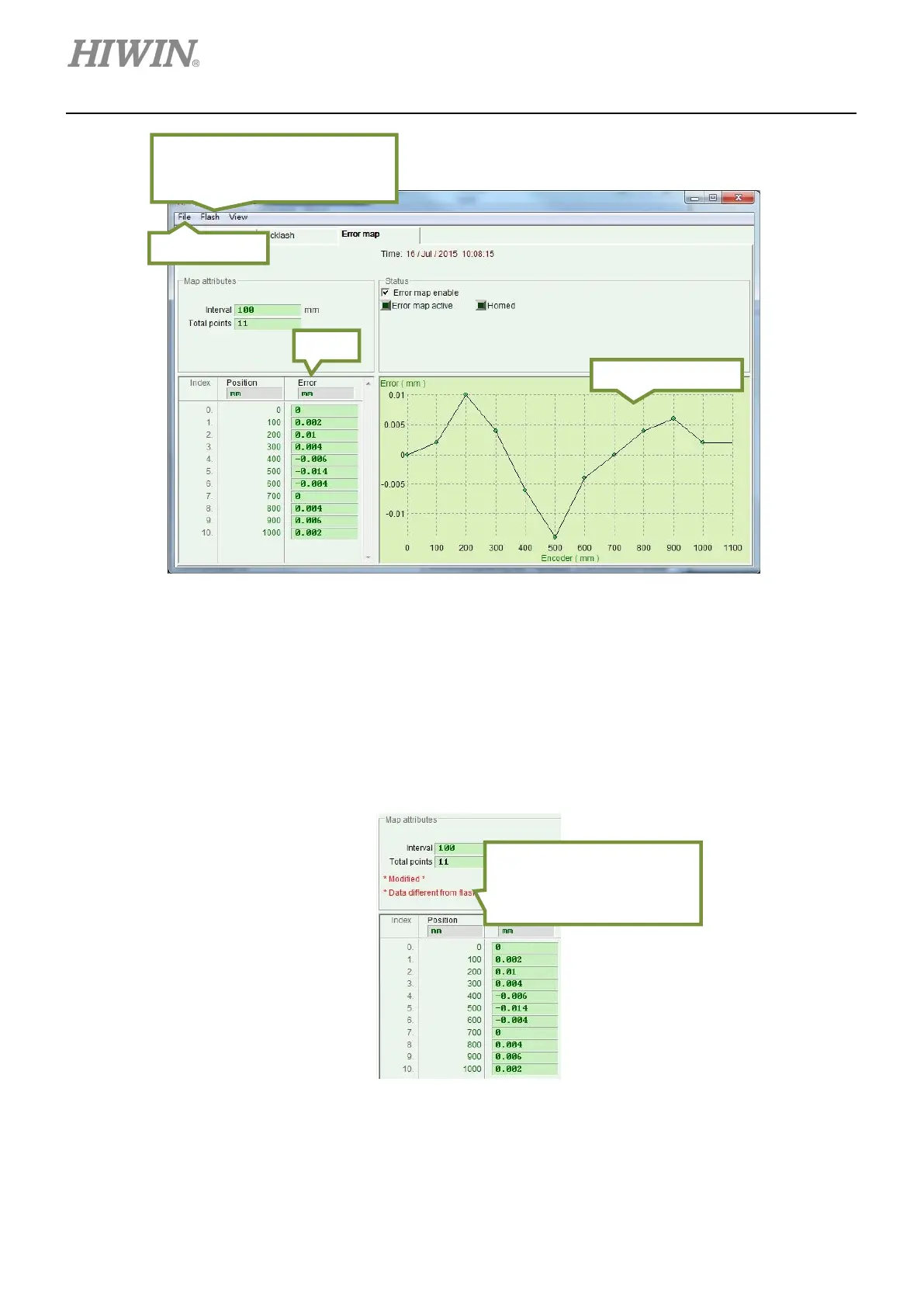
Figure 6.9.1.1 Error map page
Step 2: Set Interval and Total points. Input the errors into the fields of Error. Users are allowed to use
different units. In figure 6.9.1.1, the compensation range is from 0 to 1,000 mm. Interval is set
to 100 mm. Total points is set to 11. The errors in the fields of Error are obtained by laser
interferometer. Each value represents the positioning error at each target position. For
instance, for target position 100 mm, the actual position measured by laser interferometer is
100.002 mm.
Figure 6.9.1.2 Setting Error map function
Note:
1. After inputting errors into the fields of Error, the input values will be rounded to integer multiples of encoder
resolution. For instance, if the encoder resolution is 2 μm, input value 1 μm will be converted to 2 μm. If input
value is 0.5 μm, it will be converted to 0 μm.
Load Error map table from Flash
Save Error map table to Flash
Compare Error map table in Flash
modified compensation value
has not been saved to the
servo drive Flash.
 Loading...
