D1-N Series Servo Drive User Manual Servo Drive Configuration
HIWIN MIKROSYSTEM Corp. 5-21
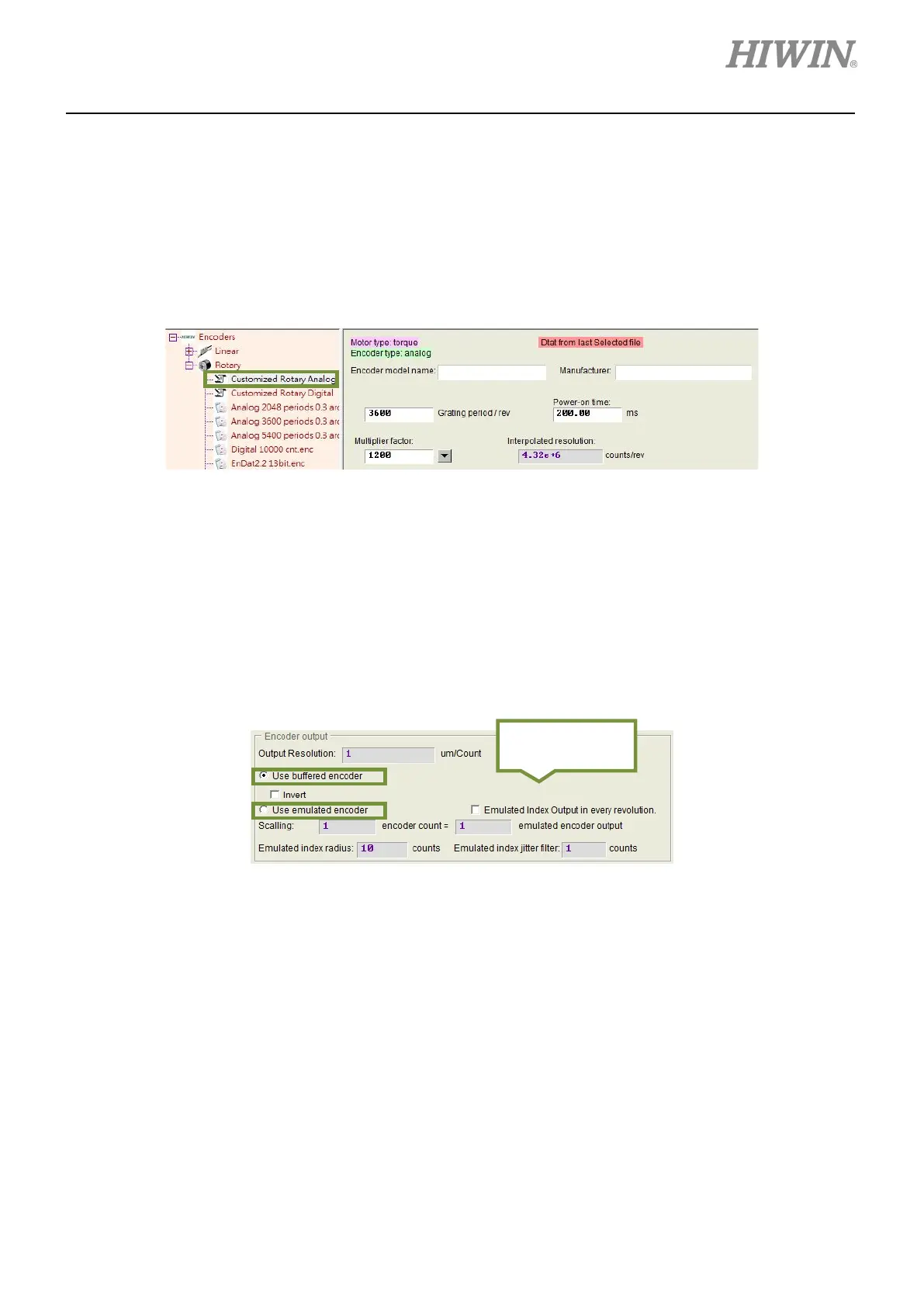
(4) Rotary-analog encoder
Set the resolution per revolution (Unit: grating period/rev). The setting value of multiplier factor must
be integer multiple of eight. The maximum setting value is 60,000. After multiplier factor is set, the
interpolated resolution (Unit: counts/rev) will be automatically calculated and displayed. D1-N servo
drive also calculates the linear resolution of the motor according to the interpolated resolution and
screw pitch.
Figure 5.2.2.2.4
5.2.2.3 Setting encoder output
D1-N servo drive outputs AqB signals via connector X6. If needed, connect to controller via connector X6.
In the encoder output setting area (figure 5.2.2.3.1), users are able to select Use buffered encoder or
Use emulated encoder. The value in Output Resolution field will be updated as different selection is
set.
Figure 5.2.2.3.1
Note:
If AC servo motor with 17-bit encoder is used, use emulated encoder to output Z-phase signal to the controller.
(1) Buffered encoder output
When buffered encoder output is selected, the signals received from the encoder will be directly
output to the controller. If needed, select Invert to invert the received signals before the signals are
output to the controller. The resolution of output signal will be shown in the same page.
Encoder output
setting area
 Loading...
