Input Calibration
3/07 UDC3500 Universal Digital Controller Product Manual 287
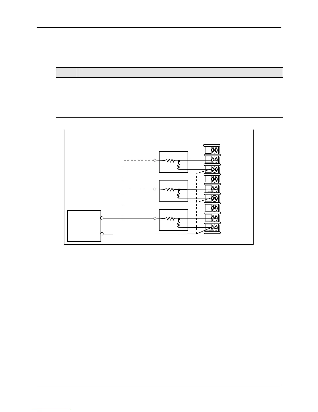
5.4.5 0 to 10 Volts or –1 to 1 Volts
Refer to Figure 5-6 and wire the controller according to the procedure given in Table 5-8.
Table 5-8 Set Up Wiring Procedure for 0 to 10 Volts or –1 to 1 Volts
Step Action
1
Connect the copper leads from the calibrator to the input to be calibrated as shown in
Figure 5-6.
2
Place voltage source at zero before switching on.
3
Following calibration, turn off the voltage source prior to disconnecting it from the
instrument.
Voltage
Source
+
30-
29+
31R
32+
33-
34R
35+
36-
28R
Input 1
Input 2
Input 3
100K
Input 1
+
100K
100K
Input 2
+
100K
100K
Input 3
+
100K
Figure 5-6 Wiring Connections for 0 to 10 Volts or –1 to 1 Volts

 Loading...


