Input Calibration
3/07 UDC3500 Universal Digital Controller Product Manual 285
5.4.4 Radiamatic, Millivolts, Volts, Carbon, Oxygen or Thermocouple Differential
Inputs
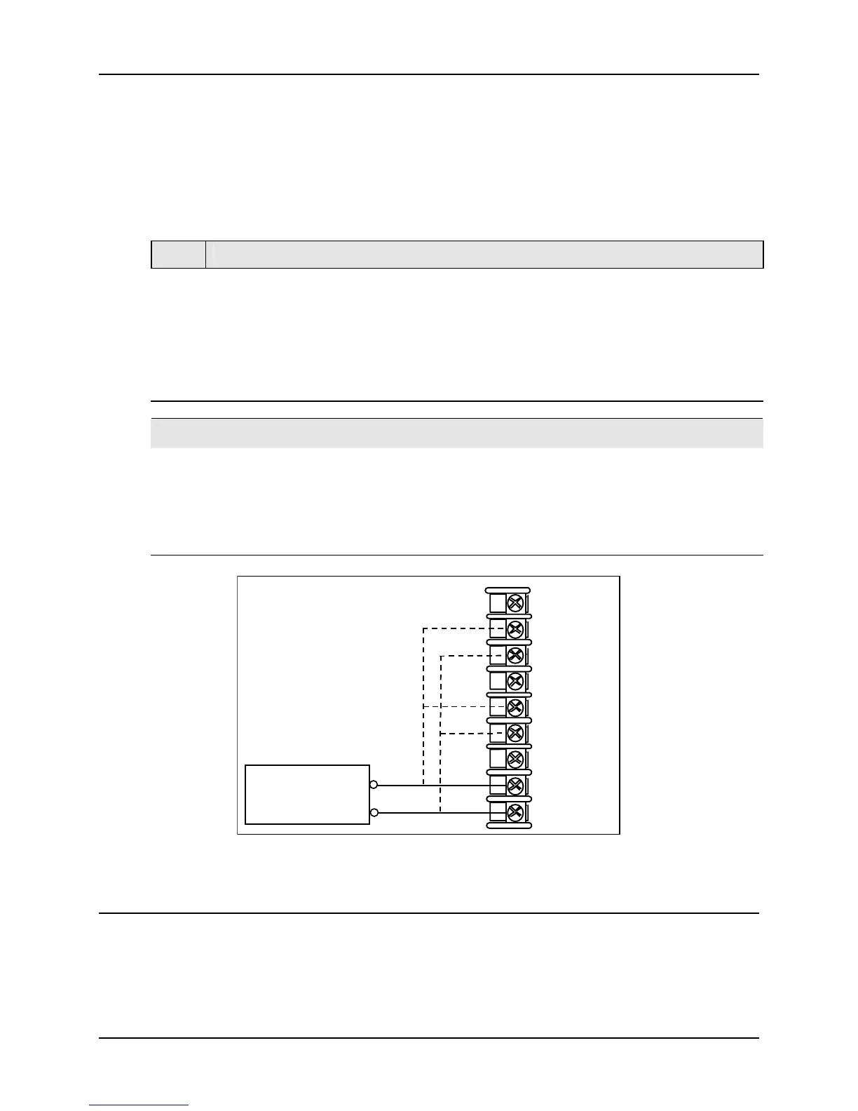
Refer to Figure 5-5 and wire the controller according to the procedure given in Table 5-6.
Table 5-6 Set Up Wiring Procedure for Radiamatic, Millivolts, Volts,
Carbon, Oxygen or Thermocouple Differential Inputs (Except 0-10 Volts and
–1 to 1 Volts)
Step Action
1
Connect the copper leads from the calibrator to the Input #1 terminals as shown in
Figure 5-5.
2
Place voltage source at zero before switching on.
3
Following calibration, turn off the voltage source prior to disconnecting it from the
instrument.
ATTENTION
For Radiamatic inputs only, set Emissivity value to 1.0.
See:
Subsection 3.15 – Configuration Set Up prompt INPUT 1, function prompt EMISSIV 1
Subsection 3.16 – Configuration Set Up prompt INPUT 2, function prompt EMISSIV 2
Subsection 3.17 – Configuration Set Up prompt INPUT 3, function prompt EMISSIV 3
Millivolt or
Volt Source
+
30-
29+
31R
32+
33-
34R
35+
36-
28R
Input 1
Input 2
Input 3
Figure 5-5 Wiring Connections for Radiamatic, Millivolts, Volts, Carbon,
Oxygen or Thermocouple Differential Inputs (Except 0-10 Volts and –1 to 1
Volts)

 Loading...


