Monitoring and Operating the Controller
226 UDC3500 Universal Digital Controller Product Manual 3/07
4.16 Auto/Manual Station
Introduction
When you select “AM STA” (auto manual station) for one of the Digital Inputs, contact
closure on the selected Digital Input causes the controller to switch to Auto/Manual
Station mode. See Section 3.22. You may have an Auto/Manual station on either loop or
on both loops.
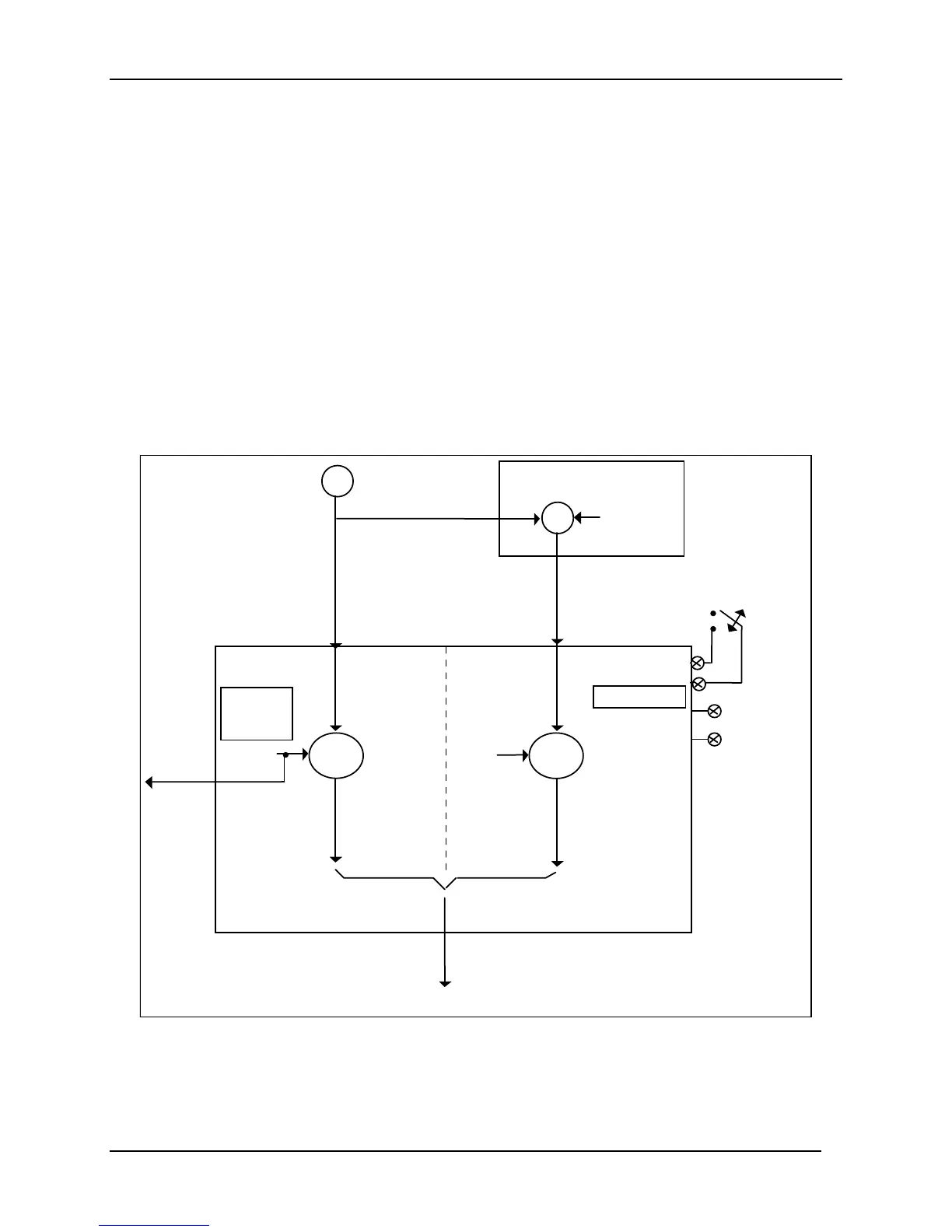
Function
As shown in Figure 4-2, State 2 is the “A/M Station mode” where the programmable
logic controller (PLC) output is sent through the Auto/Manual Station. You can switch to
manual and change the output at the controller. (It uses PID set 2.)
State 1 is the “Backup PID mode” which is triggered by opening the digital input. (It uses
PID set 1.)
T/C
T/C
PLC
PV
SP
IN1
IN2
PID A
OUT1 OUT1
Output 1
4-20 mA
To valve
ux
Output
SP1 =
new
selection
DI #1 = "AM STA"
(new
selection)
State 1:
DI #1: Open
BACKUP
PID
CONTROL
State 2:
DI #1: Closed
/M STATION
LSP = SP1
LSP = 2SP
– Direct action
– PD + MR
– SP = 2SP
– PV = IN2
– PIDSET2
PIDSET1
P =
I =
D =
same
as
PLC
Control output
4-20 mA
PVPV
larm
Output on
Manual
Mode
PD+MR
}
OPEN
CLOSED
Figure 4-2 Auto/Manual Station for Loop 1 (Loop 2 similar)

 Loading...


