Monitoring and Operating the Controller
3/07 UDC3500 Universal Digital Controller Product Manual 231
IN 1
Ratio
Bias
•
•
•
IN 2
Ratio
Bias
•
•
•
IN 3
Ratio
Bias
•
•
•
IN 4
Ratio
Bias
•
•
•
IN 5
Ratio
Bias
•
•
•
1 2 3 4
5
PV
Source
IN 2
In Alg 2
IN 3
In Alg 1
IN 4
RSP
Source
1
2
3
4
5
INPUT A
INPUT B
INPUT C
INP UT
ALGORITHM 1/2
FEEDFORWARD
INP UT A ONLY
To RS P
SP
Source
SP
PV
Remote SP
Lo c al S P
SP 1
SP 2
SP 3
To RS P
•
•
•
•
To RS P To RS P To RS P
To RS P
PID
CONTROL
ALGORITHM
Loop 2
FEEDFORWARD
SUMMER OR
MULTIP LIER
OUTPUT
Output
without
Feedforward or
Manual Mode
To Final
Control
Element
Other
Alg
None
1
2
3
4
5
Other
Alg
Output 1
Output 2
1
2
3
4
5
Other
Alg
Output 1
Output 2
OUT 2
SP 4
IN 1
IN 5
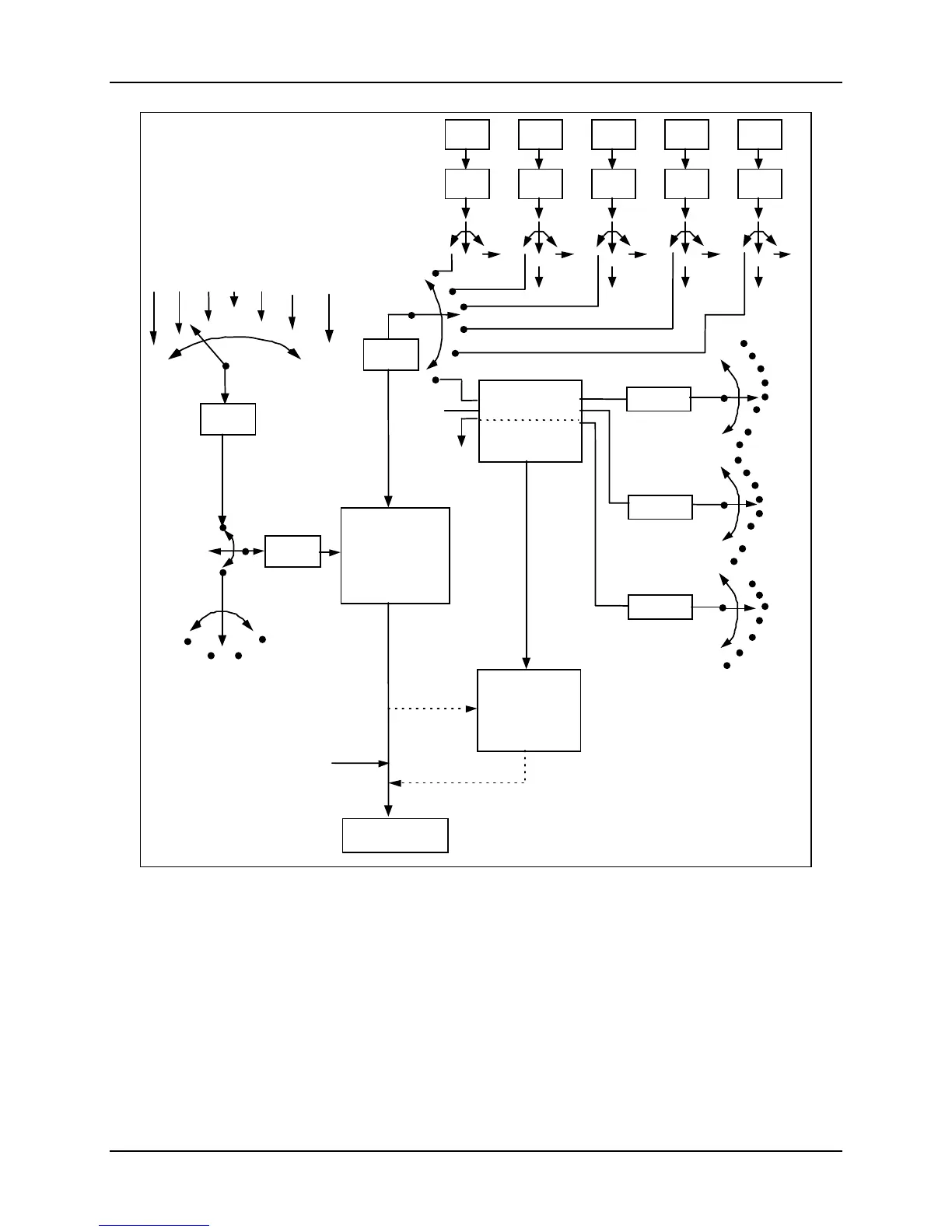
Figure 4-3 Functional Overview Block Diagram of a Single Loop (Loop #1) or Dual
Loop Controller (Loop #1 and Loop #2)
Internal Cascade Control
See Functional Overview Block Diagram Figure 4-3 for selections based on these
diagram
s.
The following rules apply for internal Cascade control:
• Loop 2 is the primary (external) loop.
• Loop 1 is the secondary (internal or slave) loop.
• Loop 1 Remote Setpoint is fixed as the Loop 2 output.

 Loading...


