Installation
38 UDC3500 Universal Digital Controller Product Manual 3/07
1
Do not run the communications lines in the same conduit as AC power.
D–
D+
COMMUNICATION MASTER
D+ (B)
SHLD D– (A)
120 OHMS
TO OTHER
COMMUNICATION
CONTROLLERS
D+D–
120 OHMS ON LAST LEG
Connect shield
to ground at one
end only.
SHLD
2
Use shielded twisted pair cables (Belden 9271 Twinax or equivalent).
2
1
26 D+ (B)
27 D– (A)
4 SHLD
UDC3500
Maximum Distance 4000 feet.
1
Do not run the communications lines in the same conduit as AC power.
D–
D+
COMMUNICATION MASTER
D+ (B)
SHLD D– (A)
120 OHMS
TO OTHER
COMMUNICATION
CONTROLLERS
D+D–
120 OHMS ON LAST LEG
Connect shield
to ground at one
end only.
SHLD
2
Use shielded twisted pair cables (Belden 9271 Twinax or equivalent).
2
1
26 D+ (B)
27 D– (A)
4 SHLD
UDC3500
1
26 D+ (B)
27 D– (A)
4 SHLD
UDC3500
26 D+ (B)
27 D– (A)
4 SHLD4 SHLD
UDC3500
Maximum Distance 4000 feet.
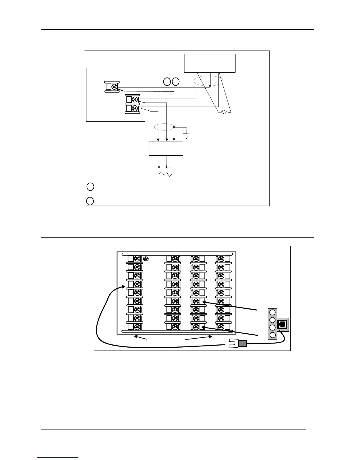
Figure 2-20 RS-422/485 Communications Option Connections
RS-422/485 connections must be “daisy-chained,” T-drop connections are not allowed.
Ethernet
Ethernet
Cable To
Hub or
4
5
6
7
8
10
11
12
13
14
15
16
17
L1
L2/N
22
23
24
25
26
27
18
19
20
21
31
32
33
34
35
36
28
29
30
24
27
9
Tie Wraps (2)
Figure 2-21 Ethernet Communications Option with Adaptor Board
Instruments equipped with the Ethernet Communications Option come with an Ethernet
Adaptor Kit. To use this kit, first remove the four screws on your instrument from
Terminal Block positions 24 through 27. Place the Ethernet Adaptor Board on to the
terminal block as shown and then secure it in place with the four long screws provided in
the kit. Route the long wire on the Ethernet Adaptor Board over to Terminal #4 on your
instrument. The RJ-45 connector on the Ethernet Adaptor Board will allow you to use a

 Loading...


