Modbus Read, Write and Override Parameters plus Exception Codes
414 UDC3500 Universal Digital Controller Product Manual 3/07
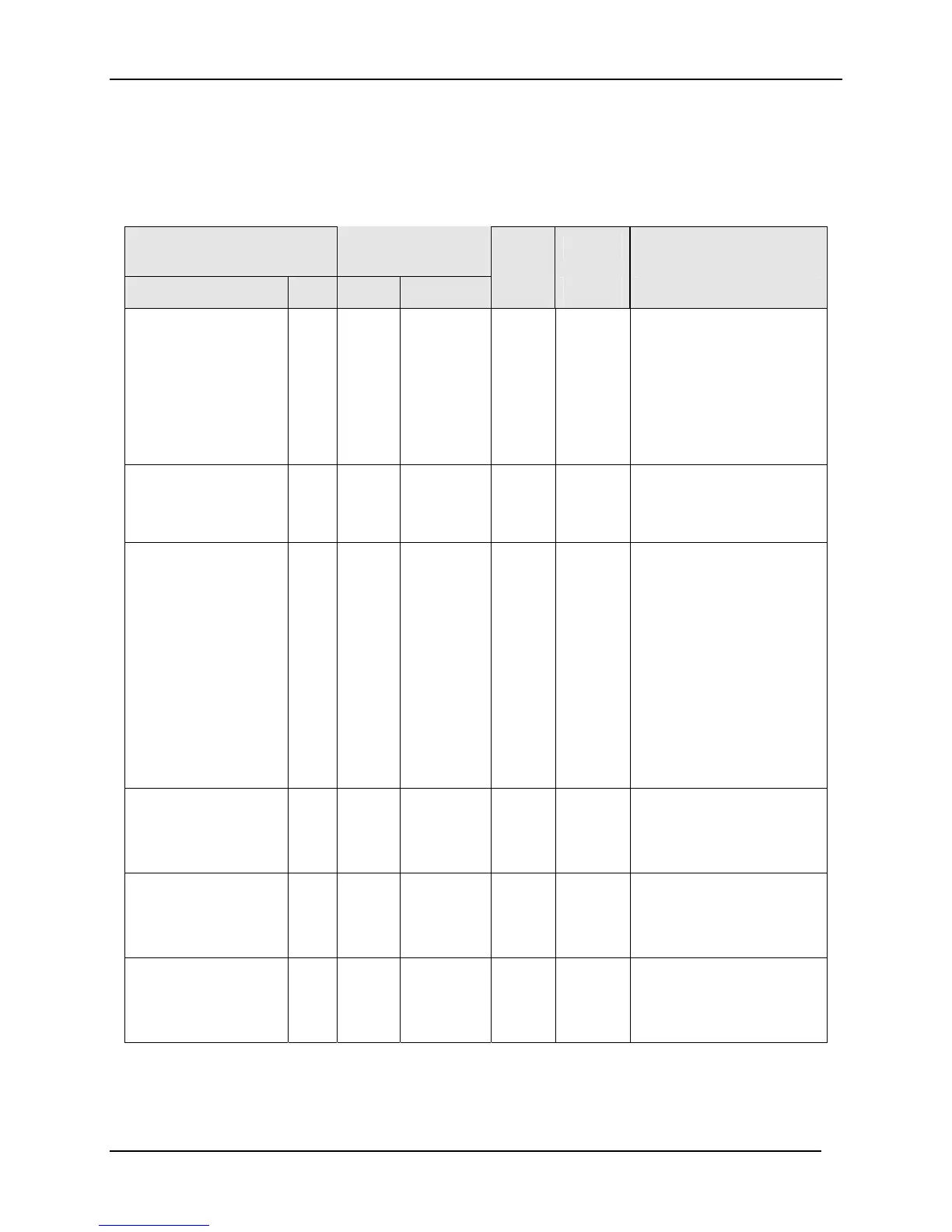
10.7.18 Control Loop 2
Table 10-27 lists all the register addresses and ranges or selections for the function
prompts in Set-up Group Control2.
Table 10-27 Set-up Group – Control2
Parameter
Register
Address
Data
Type
Access Data Range or
Enumerated Selection
Description ID Hex Decimal
PV Source Loop2 133 0185 389 INT R/W 0 = Input 1
1 = Input 2
2 = Input 3
3 = Input 4
4 = Input 5
5 = Input Algorithm 1
6 = Input Algorithm 2
7 = None
Link Modes and Set
Point
132 0184 388 INT R/W
0 = Disable
1 = AutoMan
2 = SP1
3 = AM + SP1
Tuning Parameter
Selection Loop2
172 01AC 428 INT R/W 0 = One set only
1 = 2 sets keyboard
selected
2 = 2 sets with PV
automatic switchover
3 = 2 sets with setpoint
(SP) automatic
switchover
4 = Four sets Keyboard
5 = Four sets Auto Switch
PV
6 = Four sets Auto Switch
SP
Automatic Loop2
Switchover Value
PID1 to PID2 (used
with ID 172 )
9 0109 265 FP R/W Within the PV Range in
engineering units
Automatic Loop2
Switchover Value
PID2 to PID3 (used
with ID 172 )
10 010A 266 FP R/W Within the PV Range in
engineering units
Automatic Loop2
Switchover Value
PID3 to PID4 (used
with ID 172 )
11 010B 267 FP R/W Within the PV Range in
engineering units

 Loading...


