Monitoring and Operating the Controller
232 UDC3500 Universal Digital Controller Product Manual 3/07
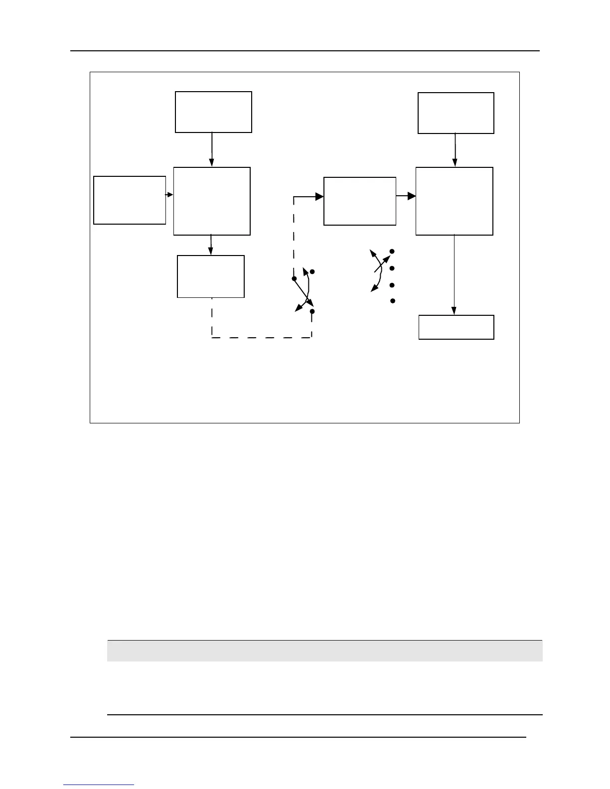
PID
CONTROL
ALGORITHM
OUTPUT
To Final
Control
Element
PV SOURCE
See Block
Diagram
LOOP 2 – PRIMARY LOOP
LOOP 1 – SECONDARY LOOP
PID
CONTROL
ALGORITHM
SETPOINT
SOURCE
INTE RN AL
OUTPUT
SIGNAL
SETPOINT
SOURCE
Block Diagram
INTERNAL CASCADE RULES
• Loop #2 is the primary (external) loop.
• Loop #1 is the secondary (internal or slave) loop.
• Loop #1 Remote Setpoint is fixed as loop #2 output.
Remote Setpoint
Local S etpo int
SP
2SP
3SP
4SP
See Loop
PV SOURCE
See Block
Diagram
Figure 4-4 Functional Overview Block Diagram of Internal Cascade Controller
Output Override
This instrument allows override of the Loop 1 output with the Loop 2 output based upon
which is larger or smaller. This can be accomplished by configuration (See Section 3.11)
or by Digital Input actuation (see Section 3.22).
The following rules apply for high/low override:
• Only one physical output is required when override is enabled. It is the output
from Loop 1 because Loop 2’s internal output is routed through the selector.
• Loop 2 output can also be available at all times if desired.
• In Manual mode, the Output may be overridden.
• Does not apply for Three Position Step Control.
• OTI on bottom display shows value of the internal Loop 1 output before any
override.
ATTENTION
The output of the unselected loop tracks the selected loop to within 5 % when in Auto mode to
eliminate windup. This tracking is done in the direction opposite to the Override Select
configuration; i.e., for High Select, the unselected output tracks within 5 % of the lower output,
and vice versa for Low Select.

 Loading...


