Installation
32 UDC3500 Universal Digital Controller Product Manual 3/07
19
20
21
22
23
24
25
26
27
10
11
12
13
14
15
16
17
L1
L2/N
4
5
6
7
8
9
+
+
–
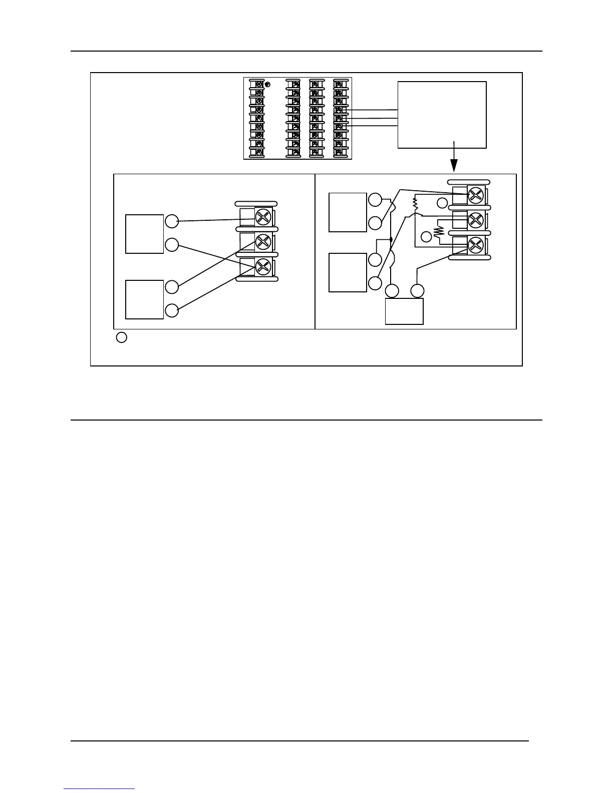
0-5V or 1-5V Connections
0-20 or 4-20mA Connections
250
31
32
33
+
+
–
1
1
31
32
33
+
+
–
High Level
Analog Input
Connections
See Below
Input 4 Source
Input 2 Source
–
+
–
+
250
Ω
Transmitter 4
Transmitter 2
–
+
–
+
Power
Supply
1
–
+
TTENTION:
Check Input 2 jumper when
replacing single input with two
HLAI.
28
29
30
31
32
33
34
35
36
18
The 250 ohm resistors for milliamp inputs are supplied with the controller when those inputs are specified.
These items must be installed prior to start up when the controller is wired. For 0-20 mA applications, the
resistor should be located at the transmitter terminals if Burnout detection is desired.
Figure 2-9 HLAI Inputs 2 and 4 Connections
See Figure 2-11 for Jumper Positions.

 Loading...


