Input Calibration
3/07 UDC3500 Universal Digital Controller Product Manual 283
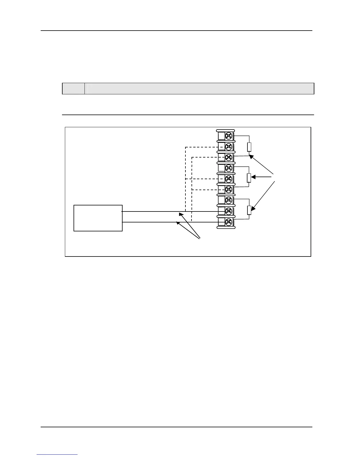
5.4.2 Thermocouple Inputs Using a Thermocouple Source
Refer to Figure 5-3 and wire the controller according to the procedure given in Table 5-4.
Table 5-4 Set Up Wiring Procedure for Thermocouple Inputs using a
Thermocouple Source
Step Action
1
Connect the thermocouple extension wires to the terminals for the input to be
calibrated. See Figure 5-3.
Thermocouple
Source
Thermocouple
Extension Wire
+
-
30-
29+
31R
32+
33-
34R
35+
36-
28R
Input 1
Input 2
Input 3
C/J Sensors
Figure 5-3 Wiring Connections for Thermocouple Inputs Using a
Thermocouple Source

 Loading...


