Introduction
3/07 UDC3500 Universal Digital Controller Product Manual 7
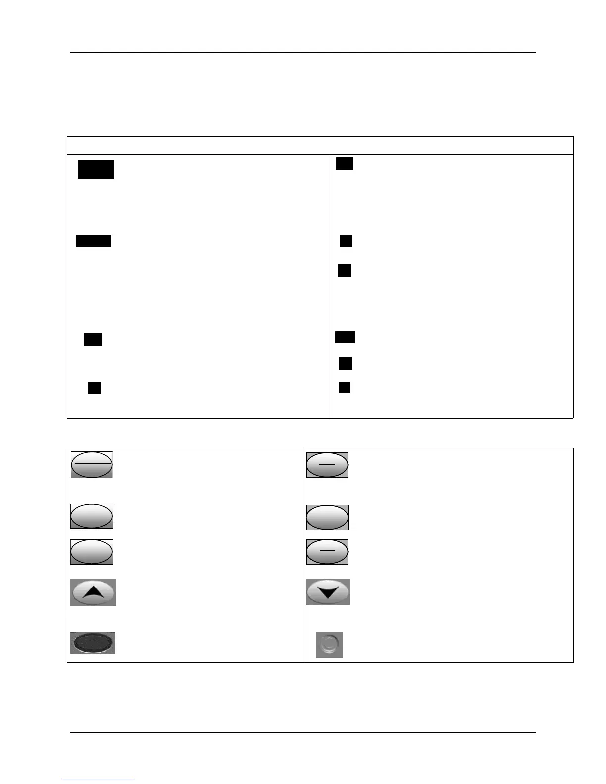
1.2.1 Function of Displays and Keys
Table 1-1 Function of Displays and Keys
Display Indicators
3200
3500
Upper display with 4 larger digits shows
Process Variable value (normal operation)
and special annunciator features. During
Configuration, the upper display provides
guidance for the operator through prompts (7
– characters)
OUT
Indicates Control Relay 1 and/or 2 on.
SP
3200
SP 3500
During normal operation, the lower display
shows key-selected operating parameters
such as Output, Setpoints, Inputs, Deviation,
active Tuning Parameter Set, Timer Status, or
minutes remaining in a setpoint ramp (4
digits). During configuration, the lower display
provides guidance for the operator through
prompts (8-characters).
FF
Or
CC
Indicates either degrees Fahrenheit or
Centigrade.
ALMALM
Indicates Alarm 1 and/or Alarm 2 conditions
exist.
MAN
Or
AA
Indicates either Manual or Auto mode.
DIDI
Indicates Digital Input 1 and/or 2 on.
SPSP
Indicates Local Setpoint #1. Also, a bar is
lighted when the setpoint being used is shown
on the lower display.
Keys and Functions
Func
Loo
1/2
Selects functions within each
configuration group. Switches between
Loop Displays for Two Loop and
Cascade units.
Man
Auto
Man
Auto
Man
Auto
Selects Manual or Auto mode.
SetupSetup
Scrolls through the configuration
groups.
SP
Select
SP
Select
SP
Select
Hold key down to cycle through configured
setpoints.
Lower
Display
Lower
Display
Lower
Display
Returns Controller to normal display
from Set Up mode. Toggles various
operating parameters for display.
Run
Hold
Run
Hold
Run
Hold
Enables Run/Hold of the SP Ramp or Program
plus Timer start.
Increases setpoint or output value.
Increases the configuration values or
changes functions in Configuration
mode groups.
Decreases setpoint or output value. Decreases
the configuration values or changes functions in
Configuration mode groups.
Infrared transceiver
NEMA4X and IP66 screw attachment (each
corner)

 Loading...


