Installation
3/07 UDC3500 Universal Digital Controller Product Manual 11
2 Installation
2.1 Overview
Introduction
Installation of the UDC3500 consists of mounting and wiring the controller according to
the instructions given in this section. Read the pre-installation information, check the
model number interpretation (Subsection 2.3) and become familiar with your model
selections, then proceed with installation.
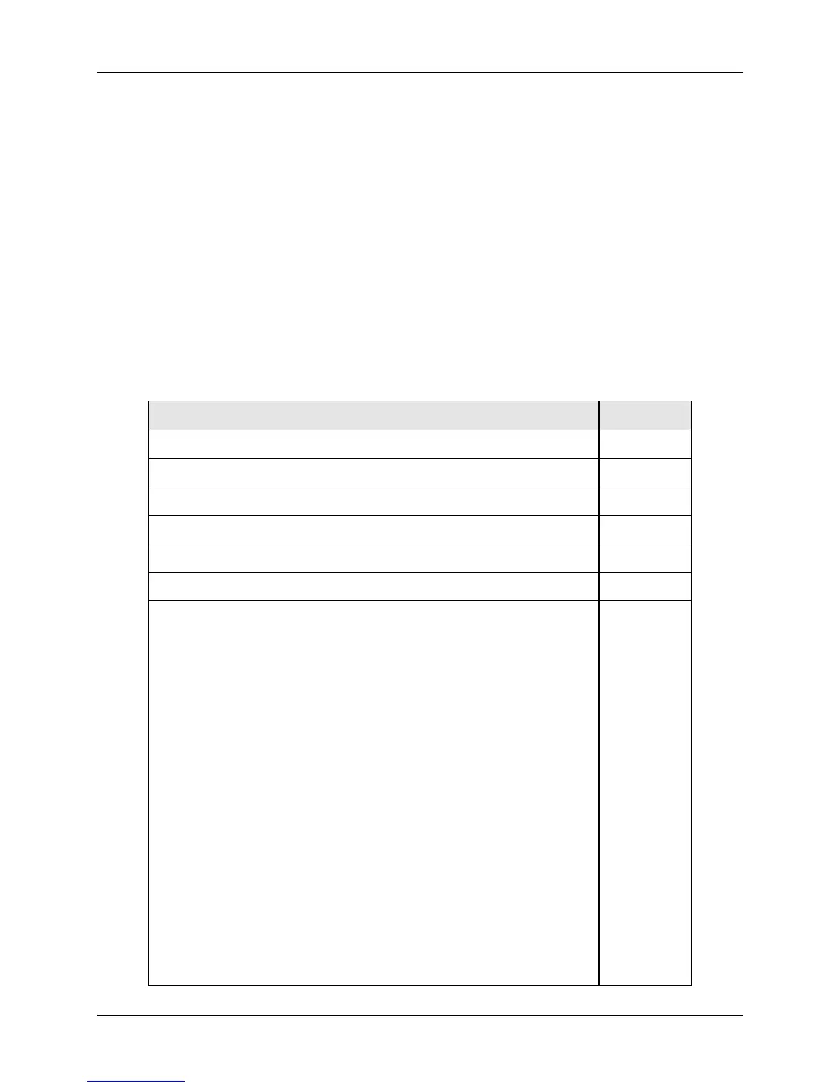
What’s in this section?
The following topics are covered in this section.
TOPIC See Page
2.1 Overview 11
2.2 Condensed Specifications 13
2.3 Model Number Interpretation 17
2.4 Control and Alarm Relay Contact Information 19
2.5 Mounting 20
2.6 Wiring 22
2.7 Wiring Diagrams
Figure 2-4 Composite Wiring Diagram
Figure 2-5 Mains Power Supply
Figure 2-6 Input 1 Connections
Figure 2-7 Input 2 Connections
Figure 2-8 Input 3 Connections
Figure 2-9 HLAI Inputs 2 and 4
Figure 2-10 HLAI Inputs 3 and 5
Figure 2-11 Optional Analog Input Jumper Positions
Figure 2-12 First Current Output
Figure 2-13 Second Current Output
Figure 2-14 Output #2 – Electromechanical Relay Output
Figure 2-15 Output #2 – Solid State Relay Output
Figure 2-16 Output #2 – Open Collector Output
Figure 2-17 Output #2 – Third Current Output
Figure 2-18 Output #2 – Dual Relay Output for Tim
e Duplex
Figure 2-19 Output #2 – Dual Relay Output for Position
Proportional or Three Position Step Control
Figure 2-20 RS-422/485 Communications Option
27
28
29
30
31
32
33
33
34
34
35
35
36
36
37
37
38
39

 Loading...


