Monitoring and Operating the Controller
224 UDC3500 Universal Digital Controller Product Manual 3/07
Keyboard Operation
Front panel keys have no effect on the digital input action in the closed state.
Digital Inputs 1 and 2 combination selections
The Digital Input combination selections listed in Table 4-19 can be used in combination
with the Digital Inputs 1 and 2 listed in Table 4-20.
If the controller is configured for either Two Loop or Cascade control, then how the
switches are allocated between the two loops must be defined. See Section 3.22.
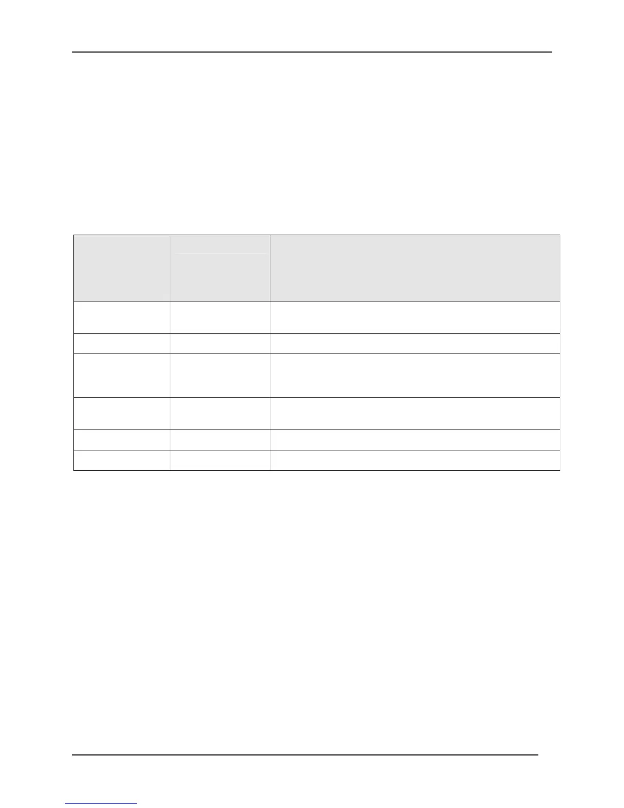
Table 4-20 Digital Input Combinations “DIG IN1” or “DIG IN2”
Selections used
in Combination
with
“DIG IN1” or
“DIG IN2”
Display Indication Action on Contact Closure
Controller returns (toggles) to original state when contact
reopens unless otherwise noted
+PID2 PIDSET 2 in lower
display
Selects PID set 2.
+ToDIR
Puts the controller into direct controller action.
+ToSP2 2SP in lower display
with the active SP
indicator blinking
Selects the second local setpoint.
+DISAT T indicator is no
longer lit
Disables Adaptive tune.
+ToSP1
Selects the local setpoint.
+RUN R indicator blinks
Starts or restarts RUN of SP Ramp/Program.
Digital Inputs 1 and 2 combination operation
There are five possible situations that can occur when working with digital input
combinations. Table 4-21 lists these situations and the resulting action when the switch is
active. In the table:
Enabled m
eans that the parameter is configured and the action will occur when
the digital input is active.
Action Disabled means that the digital input or digital combination parameter is
configured but the action cannot occur when the digital input is active because the
selected parameter is disabled.

 Loading...


