Installation
3/07 UDC3500 Universal Digital Controller Product Manual 33
19
20
21
22
23
24
25
26
27
10
11
12
13
14
15
16
17
L1
L2/N
4
5
6
7
8
9
+
+
–
0-5V or 1-5V Connections
0-20 or 4-20mA Connections
250
28
29
30
+
+
–
1
1
28
29
30
+
+
–
High Level
Analog Input
Connections
See Below
Input 5 Source
Input 3 Source
–
+
–
+
250
Ω
Transmitter 5
Transmitter 3
–
+
–
+
Power
Supply
1
–
+
TTENTION:
Check Input 3 jumper when
replacing single input with two
HLAI.
28
29
30
31
32
33
34
35
36
18
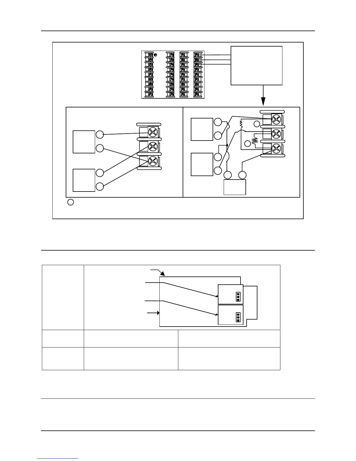
The 250 ohm resistors for milliamp inputs are supplied with the controller when those inputs are specified.
These items must be installed prior to start up when the controller is wired. For 0-20 mA applications, the
resistor should be located at the transmitter terminals if Burnout detection is desired.
Figure 2-10 HLAI Inputs 3 and 5 Connections
See Figure 2-11 for Jumper Positions.
Jumper
Location
W2
W1
MCU/Input PWA
nd Input PWA
W2
W1
3rd Input PWA
Top of unit
Jumper
Position
W1
Single Input
W2
Two HLAI
Input Types
Available
Thermocouple, RTD, Volt, Millivolt,
Milliamp, Radiamatic and
(Input 3 only) Slidewire
2
nd
Input becomes HLAI Inputs 2 & 4
3
rd
Input becomes HLAI Inputs 3 & 5
Figure 2-11 Optional Analog Input Jumper Positions

 Loading...


