Modbus Read, Write and Override Parameters plus Exception Codes
3/07 UDC3500 Universal Digital Controller Product Manual 395
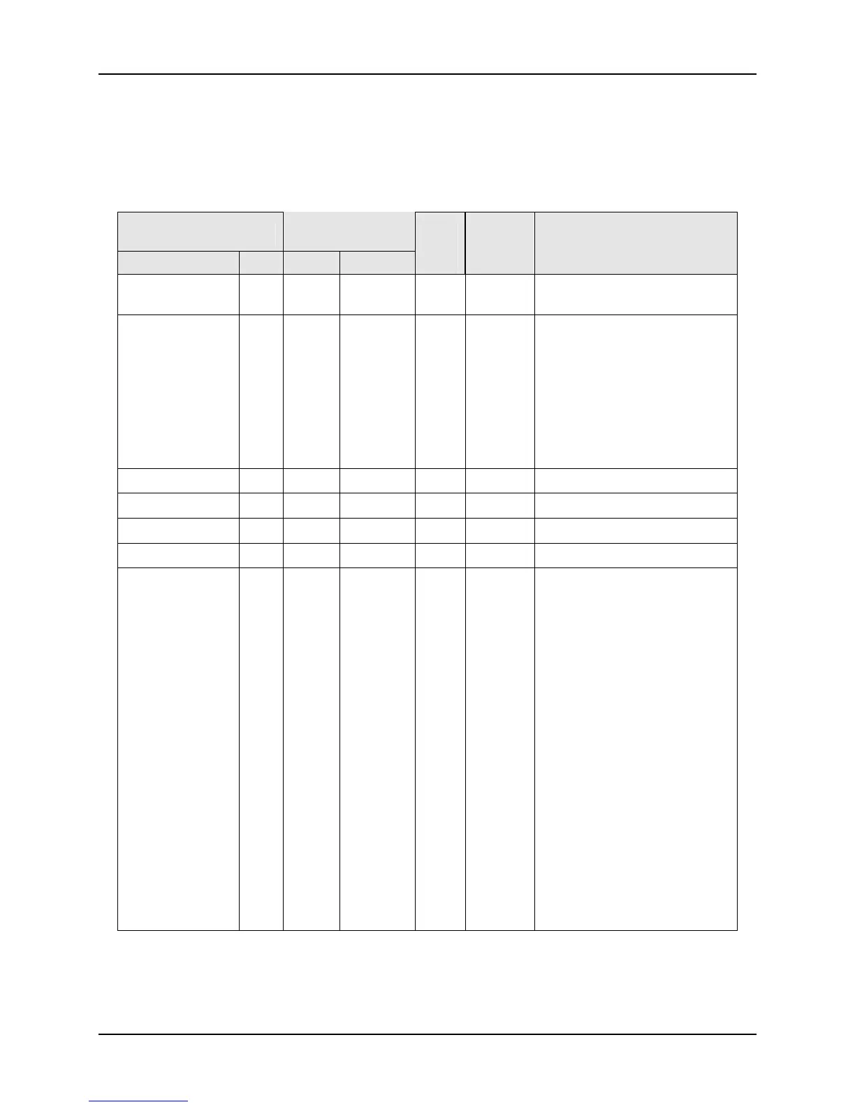
10.7.10 Logic
Table 10-19 lists all the register addresses and ranges or selections for the function
parameters in Set-up Group Logic
Table 10-19 Set-up Group – Logic
Parameter
Register
Address
Data
Type
Access Data Range or
Enumerated Selection
Description ID Hex Decimal
Logic Gates 150 4096 16534 INT R/W 0 = Disable
1 = Enable
Gate 1 Type 151 4097 16535 INT R/W 0 = Not Used
1 = OR
2 = NOR
3 = AND
4 = NAND
5 = XOR
6 = XNOR
7 = B LT A
8 = B GT A
Gate 2 Type 155 409B 16539 INT R/W Same as ID 151
Gate 3 Type 159 409F 16543 INT R/W Same as ID 151
Gate 4 Type 163 40A3 16547 INT R/W Same as ID 151
Gate 5 Type 167 40A7 16551 INT R/W Same as ID 151
Gate 1 InputA
(OR, NOR,
AND, NAND, X
OR, X NOR)
152 4098 16536 INT R/W 0 = Digital Input 1
1 = Digital Input 2
2 = Digital Input 3
3 = Digital Input 4
4 = Relay 1
5 = Relay 2
6 = Relay 3
7 = Relay 4
8 = Relay 5
9 = Gate Out 1
10 = Gate Out 2
11 = Gate Out 3
12 = Gate Out 4
13 = Gate Out 5
14 = FIX ON
15 = FIX OFF
16 = MA MODE
17 = LR SPL1
18 = ADAPT1
19 = MA MODE2
20 = LR SPL2
21 = ADAPT2

 Loading...


