Input Calibration
284 UDC3500 Universal Digital Controller Product Manual 3/07
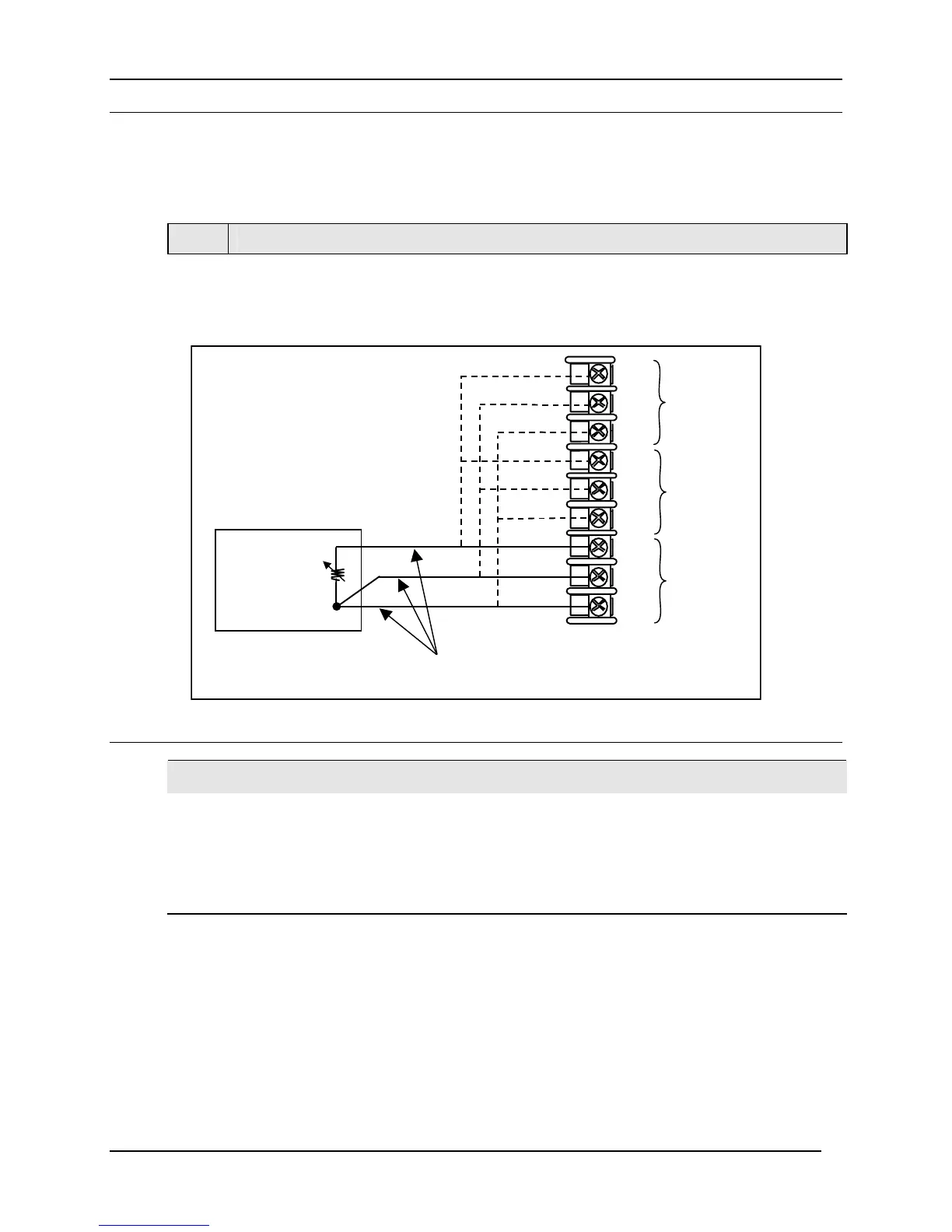
5.4.3 RTD Inputs
Refer to Figure 5-4 and wire the controller according to the procedure given in Table 5-5.
Table 5-5 Set Up Wiring Procedure for RTD Inputs
Step Action
1
Connect the copper wires to the terminals for the input to be calibrated. See Figure
5-4.
Decade
Resistance
Box
Copper Leads
Equal Length
30-
29+
31R
32+
33-
34R
35+
36-
28R
Input 1
Input 2
Input 3
Figure 5-4 Wiring Connections for RTD (Resistance Thermometer Device)
ATTENTION
Decade Resistance Boxes are usually not accurate enough to meet the 0.02% accuracy
requirement noted in Table 5-2. This can be overcome by performing a four-wire resistance
measurement with a precision DMM and then adjusting the Decade Box to the correct zero and
span resistance values as given in
Table 5-1. Determine the proper zero and span resistance
settings prior to attaching the Decade Box to the instrument. For best accuracy, measure with
the DMM connected to the wire ends rather than directly to the Decade Box.

 Loading...


